Factors on which the Resistance of a Conductor Depends

Introduction

A conductor’s ability to resist the flow of electric current through it is known as resistance. Resistors are parts that are used to stop the flow of electrons. Due to the attraction between positive particles and negative electrons, the positive conductor particles obstruct the passage of electrons. The flow of electricity is resistant as a result of this obstruction. Ohms are the units used to measure resistance. There are two categories of electrical resistance: static resistance and dynamic resistance. The length of the conductor, cross-section area, temperature, material, etc. are the parameters that affect or depend on resistance.

lead magnet

Resistance of Conductor

Resistance is defined as a conductor’s ability to obstruct the passage of current. The conductor’s resistance is expressed mathematically as the relationship between the current flowing through it and the potential difference along its length.  The movement of electrons across a conductor is known as electric current. Because of their attraction to one another, positive conductor particles obstruct the flow of electrons, which results in resistance to the movement of electricity. Resistance can be used to disperse voltage in a current as well as control the flow of electrons.

The resistivity of the conductor depends on

The ability of a material to resist electrical conduction is known as its resistivity. Resistivity is utilised to offset the effects of size on resistance. It is a non-size dependent material attribute. The resistivity of a conductor is influenced by elements such as temperature, alloying, cold work, age hardening, and mechanical stress. For most materials, resistance rises with temperature. Semiconductors are an exception, as their resistance increases with temperature.

Resistance also depends on the temperature of the conductor. As the temperature increases the resistivity increases.

\[R{\rm{_T}} = {\rm{ }}R{\rm{_0}}(1{\rm{ }} + \alpha \Delta T)\]

R = final resistance, \(R_0\) = initial resistance, and α = temperature coefficient 

Check out our Science tuition to strengthen your Science concepts. Study Science Topic for classes 6th,7th, and 8th.

Resistance depends on temperature

The thermal energy of electrons rises with the temperature of metal conductors, which also raises the frequency of collisions between free electrons. As a result, they begin to move randomly, making it challenging to drift for conduction in a specific direction. The conductor’s resistance increases as a result. As a result, resistance rises as temperature rises for a metal conductor. Increasing current frequently results in temperature rise.

Conductor resistance formula

The resistance of a conductor is directly proportional to the length of the conductor (l). Thus, on doubling its length, resistance will be double, while on halving its length, resistance will be half. Also, the resistance of a conductor is inversely proportional to its cross-section area (A).

Since, \[R\propto L\]

And, \[R\propto \frac{1}{A}\]

Hence, \[R\propto \frac{L}{A}\]

Or, \[R = \rho \frac{L}{A}\]

Where R is resistance in ohm, L is length or conductor in meter, A is cross-section area in square meter and ρ is the resistivity constant in ohm per meter.

The bigger the value of resistance, the more it opposes the current flow. The value of resistance is given in Ω.

Temperature effect on resistance

A material’s resistivity changes with temperature. Resistance varies depending on the conductor, semiconductor, and insulator’s temperature. Resistance is influenced by temperature in two different ways: for metal conductors, it rises as the temperature rises, and for insulators, it falls as the temperature rises. At high temperatures, semiconductors have great conductivity.

Resistance of a Conductor.
Solved Problems

Problem 1: What is the resistance of the circuit having length 10 cm and area 100 cm$^2$ having resistivity of 1.8 Ω.m?

Solution:

Length of circuit = 10 cm

Area of circuit = 100 cm$^2$

Resistivity = 1.8 Ω.m

The Formula used,

\(R = \rho \frac{L}{A}\)

\(\Rightarrow R = 1.8~\Omega.cm \frac{10~cm}{100~cm^2}\)

\(\Rightarrow R = 0.18~\Omega\)

Problem 2: What is the cell constant of the circuit when the conductivity is 20 Siemens/m having resistance 100 Ω?

Solution:

Resistance = 100 Ω

Conductivity = 20 Siemens/m

Cell constant =?

The Formula used,

\(R = \frac{Cell Constant}{Conductivity}\)

\(\Rightarrow Cell~Constant = Conductivity \times R\)

\(\Rightarrow Cell~Constant = 20~Siemens/m \times 100~Ω\)

\(Cell~Constant = 2000~m^{-1}\)

lead magnet

Frequently asked questions

1.What is the importance of resistance in electricity?

Ans: Resistance is a crucial component of electrical circuits; as resistance increases, current flow becomes more challenging, and as resistance decreases, current flow becomes easier. The resistance is a crucial component in conduction. Conduction greatly benefits from electron flow. The conductor turns into a semiconductor and an insulator as a result of an increase in resistance.

2. Do conductors have high or low resistance?

Ans: Insulators have a very high resistance to electrical current, compared to conductors’ extremely low resistance. Resistance turns become an insulator as it rises. Since there is no interruption to the high flow of electrons, the conductor’s resistance is very low. Conduction and resistance are inversely correlated.

3. Is it a light bulb resistor?

Ans: Despite not actually being resistors, light bulbs exhibit resistive behaviour. Electrons cannot pass through resistors, which also transform energy into another form. The process by which electricity passes through a light bulb to produce light and heat is the same. The light bulb’s filament serves as a resistor. The law of conservation of energy states that as energy cannot be created or destroyed, it can only be transformed from one form to another.

AC Voltage Capacitor

Introduction

We know that a capacitor consists of two plates of conductors separated by an isolated distance and is also known as a dielectric. The capacitor limits or regulates the current when connected to an alternating current source, but it does not completely prevent charge drift. The capacitor gradually charges and discharges as the current reverses throughout each half-cycle. The highest charging current occurs while the capacitor’s plates are not charged, hence the charging process is not linear or instantaneous. Similar to the capacitor, once it is completely charged, its charge starts to drop dramatically. The capacity of a capacitor to hold a charge on its plates is known as capacitance. When a capacitor is connected to a voltage source in a DC circuit, current flows for the brief period of time required to charge the capacitor. The voltage across the conductive plates increases as charge accumulates on them, reducing the current. The circuit current zeroes out after the capacitor is fully charged.

Capacitance in AC circuits and capacitive reactance

A capacitor’s estimated capacity to store energy in an AC circuit is known as capacitance. The ratio of an electric charge to the corresponding difference in its electric potential is known as capacitance.

$$C=\frac{d Q}{d V}$$

Where dQ and dV are the charge and potential difference across capacitors, respectively. The capacitance may also be defined as the property of a capacitor to store the charge. The correlation between charging current (I) and the capacitors at which the capacitors supply voltage changes is given by 

$$I=C \frac{d Q}{d V}$$

Capacitive reactance

Capacitive reactance is the resistance to the flow of electricity through the AC capacitor. It is calculated in ohm and denoted by \(X_C\) and measured in the units of Ω. It is calculated mathematically using the provided formula.

$$X_C=\frac{1}{2 \pi f C}=\frac{1}{\omega C}$$

Where f is the frequency, C is the capacitance and ⍵=2πf.

The ratio of the effective current to the voltage across the capacitor is another way to describe the capacitive reactance. We get the conclusion that capacitive reactance is inversely linked to frequency from the aforementioned connection. This implies that a drop in frequency across the capacitor will result in a decrease in capacitive reactance, and vice versa.

Improving your Science concepts. Study Science Preparation for classes  6th, 7th, and 8th.

How does a capacitor work in AC?

The capacitor is directly linked to the AC supply in an AC circuit. The capacitor goes through a process of charging or discharging and blocks DC when an AC source is applied. The capacitor also partially obstructs the AC signal. Reactance is the term used to describe a capacitor’s properties in reaction to an AC signal. The capacitor has a short circuit in AC.

AC Capacitor Circuits?

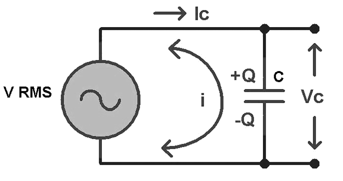
An AC capacitor circuit directly connects the AC supply to the capacitor to allow current to flow through the circuit. The capacitor’s plates are constantly being charged and discharged as a result of the AC supply.

Capacitor connected across a circuit.
An capacitor is connected to an ac circuit.

Role of capacitor in AC circuit

As long as there is a source, the capacitor will constantly charge and discharge. The time constant, however, governs whether it fully charges (transforms electrical energy into charge to store between two plates) or fully discharges (charges into electrical energy). We must use a load to charge a capacitor. The time constant is RC, where C is the capacitance and R is the load resistance of the circuit. The capacitor starts to charge when a power source is placed in its path. When fully charged, it will wait for the appropriate time to release the energy it has accumulated.

Role of capacitor in DC circuit

The capacitor starts to charge as soon as a DC supply is connected since DC sources have continuous voltage. Once fully charged, it will wait for the right time to release the charge it has saved. The outcome is that it is an open circuit after being fully charged. As a result, the capacitor acts as a component of an open circuit. The charge is continually charged and discharged with an alternating current, though, due to the variable voltage. The capacitor, therefore, performs the role of a resistor. In this instance, reactance is used in place of resistance, and a capacitor’s reactance is equal to

$$
\frac{1}{2 \pi f C} .
$$

The function of a capacitor in an AC circuit

Electrical circuits contain capacitors, which store electrical energy and raise the circuit’s power factor.

$$
\text { Power factor }=\frac{\text { Real Power }}{\text { Apparent Power }}
$$

AC through the capacitor (Derivation)

Suppose Q is the charge on the capacitor at a given time t, and the instantaneous voltage is V across the capacitor, then we can write,

$$
V=\frac{Q}{C}
$$

The voltage across the source and the capacitor is uniform. Then, according to Kirchhoff’s loop rule

$$
V=V_m \sin \omega t
$$

From the above two equations, we can write that,

$$
V_m \sin \omega t=\frac{Q}{C}
$$

Again,

$$
I=\frac{d Q}{d t}
$$

$$
I=\frac{d}{d t}\left(C V_m \sin (\omega t)\right)=\omega C V_m \cos (\omega t)
$$

Now, as we know,

$$
\begin{gathered}
\cos (\omega t)=\sin \left(\omega t+\frac{\pi}{2}\right) \\
I=I_m \sin \left(\omega t+\frac{\pi}{2}\right) \\
I_m=\frac{V_m}{\left(\frac{1}{\omega C}\right)}
\end{gathered}
$$

\(\frac{1}{2 \pi f C} \) is the capacitive reactance and is denoted by \(X_C\).

So,

$$
I_m=\frac{V_m}{X_C}
$$

Summary

The capacitor is an electrical part that creates a direct connection with the voltage of the source of alternating current. The capacitor alters its charge or discharge in response to a change in the supply voltage. With no real current travelling through the capacitor, the circuit’s current will first flow in one direction before switching to the other. In a circuit with direct current, things are different. The capacitor plate contains both positive and negative charges when current passes through it when it is linked to a direct current circuit. In many diverse sectors, including energy storage, filters, rectifiers, and other things, capacitors are used. Additionally, it is utilised in circuits to increase voltage and smooth out current swings.

Frequently Asked Questions

1. What is capacitive reactance?

Ans: The capacitive reactance in an electric circuit is the resistance that a capacitor presents to the flow of alternating current

2. State Kirchhoff’s voltage law.

Ans: The algebraic sum of potential differences and electromotive forces is zero in a closed loop.

3. State the role of the capacitor in the AC circuit.

Ans: The charge is continually charged and discharged in an AC circuit due to variable voltage. The capacitor, therefore, performs the role of a resistor. In this case, reactance is used in place of resistance, and a capacitor’s reactance is equal to \(\frac{1}{2 \pi f C} \).

4. State the role of the capacitor in the DC circuit.

Ans: The capacitor starts to charge as soon as a DC supply is connected because a DC source’s voltage is constant. Once fully charged, it will wait for the right time to release the charge it has saved. The outcome is that it is an open circuit after being fully charged. As a result, the capacitor acts as a component of an open circuit.

5. What is an electrolytic capacitor?

Ans: An electrolytic capacitor is a capacitor in which ion mobility makes conduction feasible. A liquid or gel with a high ion concentration is called an electrolyte.

Resistance of a System of Resistors

Introduction

Electrons encounter resistance when they go through a conductor because of the molecules’ attraction forces. The nature of the material determines how much of this resistance is provided. The resistance of the material determines how much electricity flows as a result of voltage differences. Ohm’s law relates electric current (I), voltage (V), and resistance such that,

V = IR

Electrical resistors are devices that provide resistance to an electric circuit. The zigzag symbol in an electrical circuit diagram stands in for a resistor.

System of Resistors

Systems of resistors can be arranged in series or parallel.

1. Resistors in Series Arrangement:

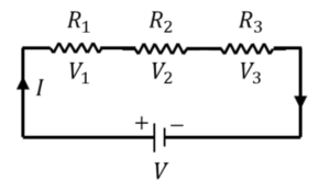
The resistors are arranged in this configuration along the current’s path, one after the other (end to end). As the current passes through the first resistor, its output current enters the second resistor as an input, and the second resistor’s output is then transferred to the third. The equivalent resistor, whose total equivalent resistance is simply the sum of the individual resistance of all the resistors linked in series, may replace all the resistors in a circuit. The equivalent resistor’s formula is:

Each resistor in a series circuit receives the same amount of current, and the voltage across each resistor varies proportionally to its resistance.

The total voltage of the circuit is equal to the sum of the voltage across each resistor when the total current, I, in the circuit is multiplied by both sides of the equation.

2. Resistors in Parallel Arrangement:

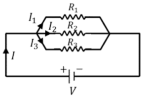
All the parallel resistors in this configuration share an input lead and an output lead, i.e., they are connected across each other. Each resistor in a parallel combination has the same voltage across it, which is the same as the circuit’s overall voltage. At a junction, the electric current is split based on the resistance of each resistor. At the output junction, the whole output current is combined once more and flows through the circuit.

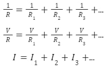
Equivalent resistance in parallel is given as follows:

Since the total voltage on each side of the equation is the same, the voltage across each resistor is also the same. We can see that the circuit’s total current, I, equals the sum of the currents flowing through all the resistors.

Summary

Small electrical components known as resistors provide resistance to the passage of electricity in an electric circuit. A circuit can link many resistors in series or parallel configurations. If many resistors are replaced with a single resistor that has the same resistance as the combination, the equivalent resistance of that resistance is the same as the resistance of the series and parallel combination of resistors. The combination formula for series resistors is, Req.=R1 + R2 + R3 +…, and for the parallel combination 1R = 1R1 + 1R2 + 1R3 +…

Frequently Asked Questions

1. What are the Factors on which the Resistance of an Object Depends?

Ans: An object’s electrical resistance is determined by the characteristics of its material and form. The formula takes into consideration these elements:
R= ρ (l/A)
Where A is the cross-sectional area of the material, Rho is its resistivity, and l is the length of the material through which electricity is flowing.

2. What is Electrical Conductivity?

Ans: The inherent capacity of a substance to carry electricity is known as electrical conductivity. It shows how readily electricity can go through the substance. The symbol for conductivity is (sigma), which is just the reciprocal of resistance such that: σ = 1/ ρ
Conductivity equals. Like resistivity, which is a broad attribute of a material that depends on its size. Air is a superb insulator with very low conductivity, whereas metals are typically good conductors with high conductivity and low resistance. Even at temperatures close to absolute zero, superconductors exhibit conductivity.

3. What is the SI unit of Resistivity and Conductivity?

Ans: The most used system of measuring in contemporary times is the SI unit or the International System of Units. The globe uses this contemporary metric system, which is utilised in all languages.
The SI unit of resistivity- ohm metre (Ω.m).
The base SI unit of resistivity- kg.m³.s−³.A-².
The SI unit of conductivity- siemens per metre (S/m).
The base SI unit of conductivity- kg-¹.m-³.s³.A².