LC Oscillations

Introduction

Electronics is a branch of physics that focuses on the behavior of electrons in electronic circuits. Unlike classical electrical engineering, electronics employ active devices as components. Note that active devices are devices that can control the flow of electricity in a circuit. On the other hand, passive components only consume electricity but cannot regulate it. Vacuum tubes which have the ability to control the flow of electrons, were initially fundamental to electronics but that technology is now obsolete. Today, you can create much more intricate circuits in much smaller form factors using transistors. 

An electric circuit is a closed path through which electric current can flow. Electrical components such as transistors, resistors, capacitors, and inductors are utilized in these circuits. Electronic devices, including computers, are constructed from thousands of electric circuits composed of these electronic components.

What is oscillation?

You have already come across hundreds of oscillations in your daily life. The term “oscillation” refers to the repetitive to and fro motion of a device or quantity. When a particle oscillates, it vibrates about an equilibrium position periodically. Common examples of oscillation you might be familiar with include the pendulum of a clock, your heartbeat, and the movement of strings in musical instruments. The pendulum moves to and fro from its mean position. Similarly, in a slinky, the spring extends and contracts rhythmically. An oscillation can be represented using a sine wave, whose value itself oscillates about 0. Oscillations can be free, damped, or forced.

Inductor

An inductor is a passive electronic component that converts electrical energy into magnetic energy and stores it. It is made up of a coil of wire that is generally wrapped around a given core but can be made without a core as well. An inductor works on the principle of electromagnetic induction, which is related to the generation of a magnetic field due to a changing current. 

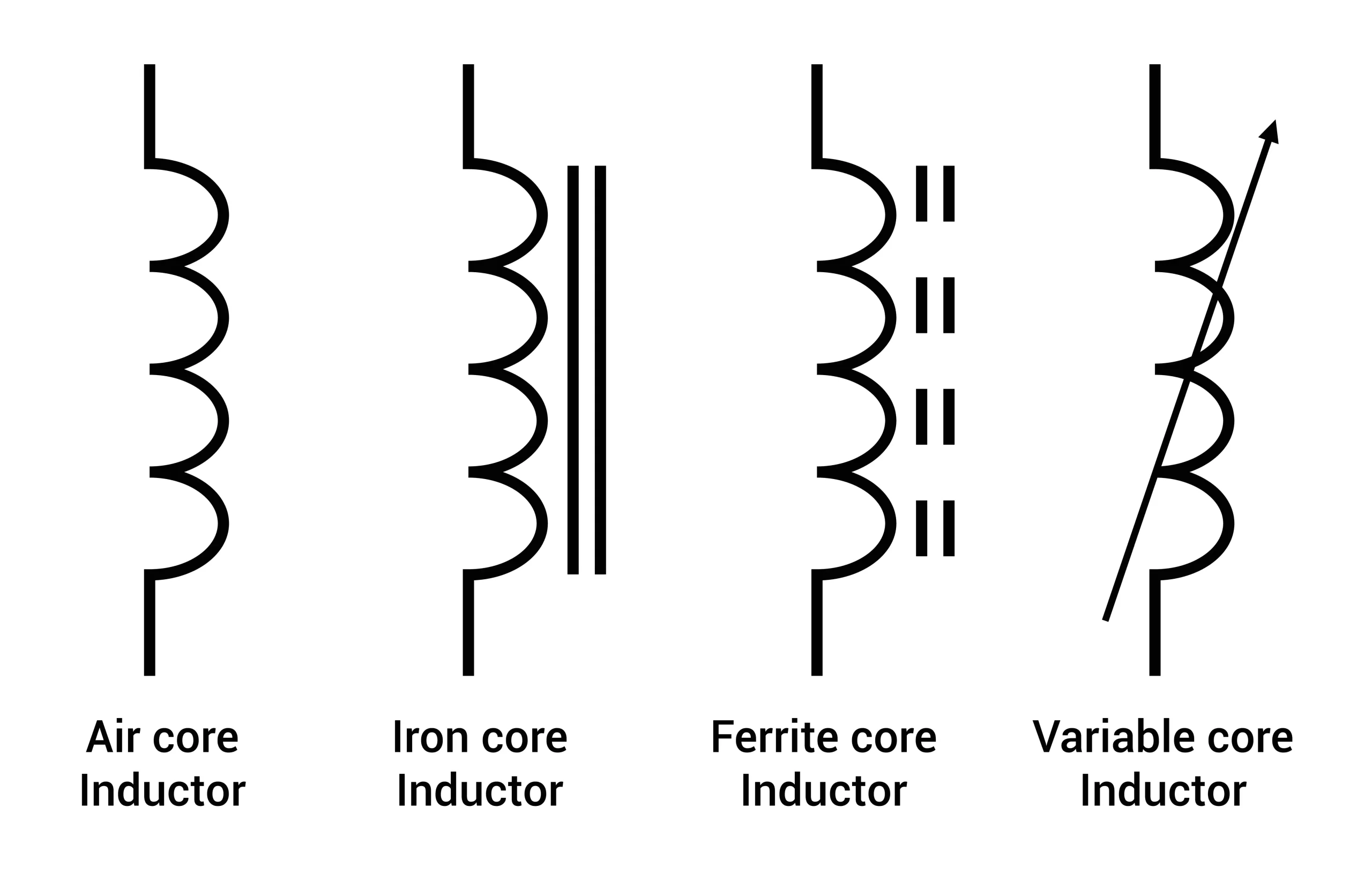
Since an inductor is in the form of a coil, when current going through it changes, the loops of the coil resist the corresponding change in magnetic field. A quantity that characterizes inductors is the inductance. It is defined as the ratio of induced EMF to the change in current over time. The figure below shows a few common inductor types:
LC Oscillations

Inductor types

The increase in current creates a magnetic field in the inductor. This magnetic field reduces when the current through it decreases and the energy stored in the magnetic field is converted into electrical energy. Thus, an inductor can store energy in the form of a magnetic field.

Capacitor

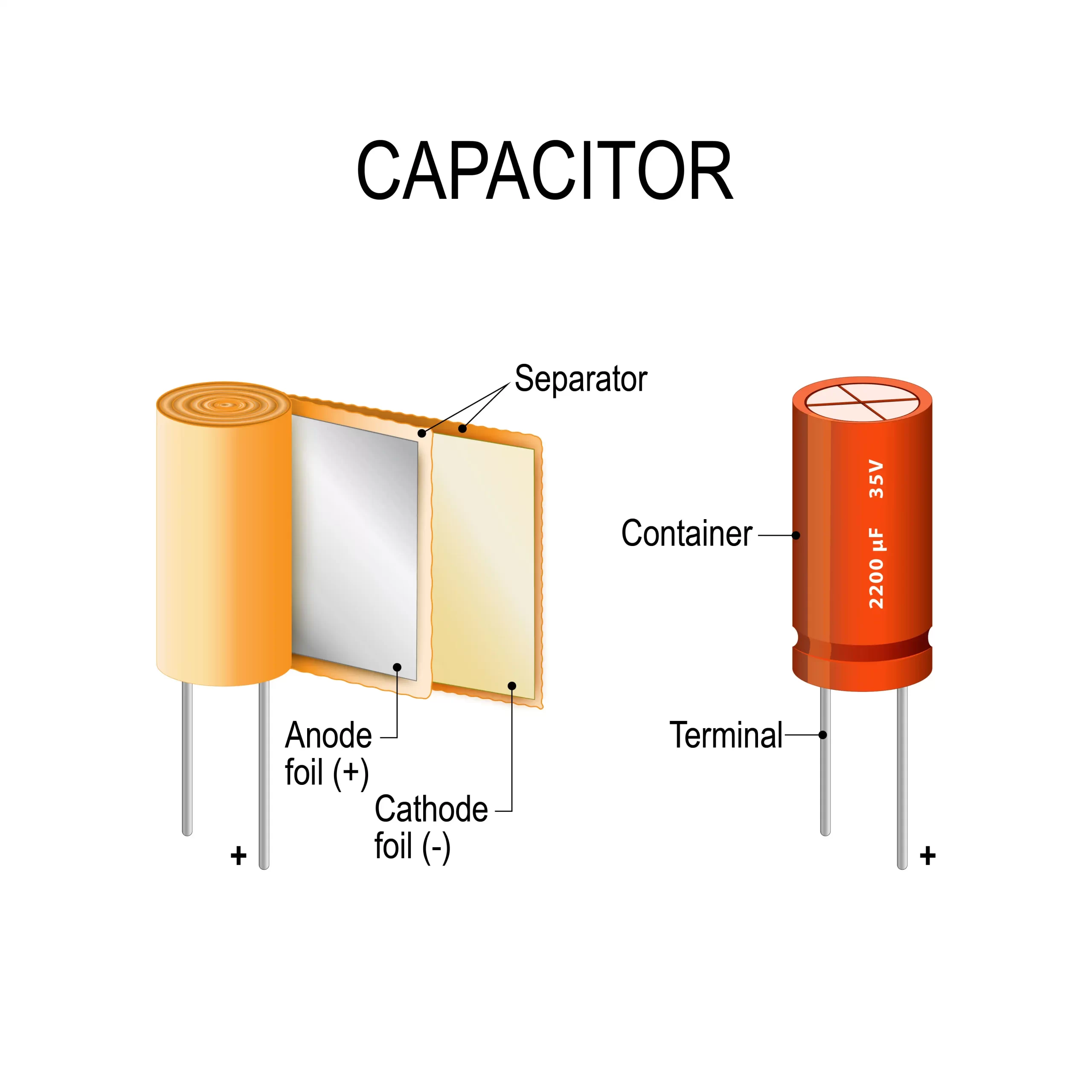
Capacitance is the ability to store electric charge and capacitors are devices that facilitate this. Generally, they are made of two conducting plates separated either by air or by some other dielectric material like ceramics, plastics, mica, etc. 

When a capacitor is connected to a DC source, electrons move from the negative terminal and accumulate on the conducting plate, inducing a positive charge on the other plate. The dielectric material in between the plates prevents electrons from crossing the barrier. This way, electrons get stored on the plates and the energy thus stored can be utilized later. Mathematically, capacitance is measured using the following formula:

The following diagram shows a capacitor:
Capacitor

LC oscillator

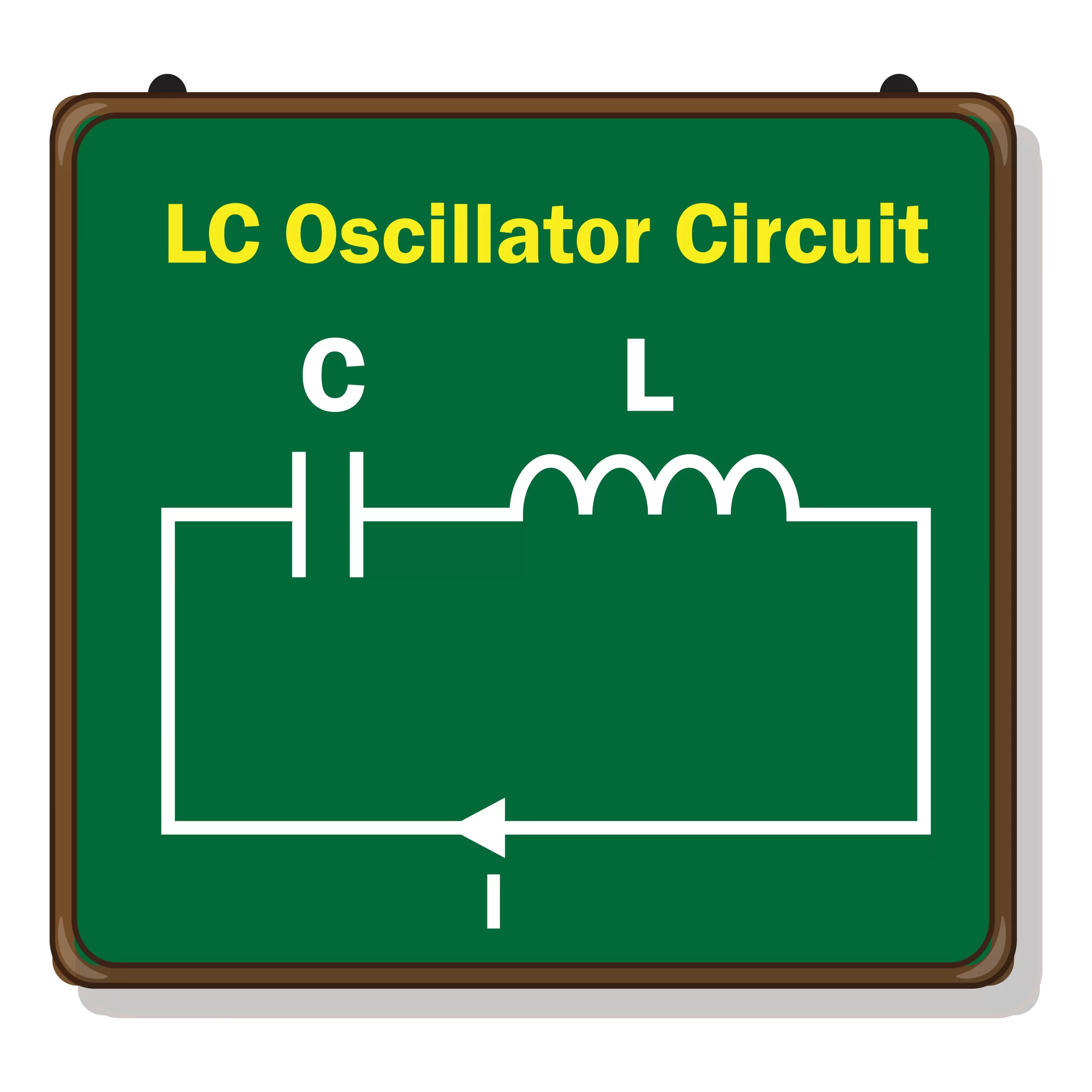
An LC circuit is so named because it contains an inductor and a capacitor. Capacitance is depicted by C while inductance is depicted by L, hence the name LC circuit. An LC circuit is also sometimes referred to as a tank circuit. An LC circuit can act as a resonator that stores energy and then oscillates at a particular frequency using positive feedback without external influence.
LC Oscillator

Working of LC oscillator

  1. In the circuit depicted in the figure above, we have an inductor and capacitor connected in series.
  2. When voltage is applied, the capacitor starts developing a charge. In this time period, the inductor does not receive anything.
  3. When the applied voltage is removed, the energy stored in the capacitor flows to the inductor and the capacitor discharges.
  4. Once the capacitor has been completely depleted, the inductor carries all the energy and it removes it into the circuit. This charges the capacitor in the opposite direction till all energy is transferred to it.
  5. This cycle repeats to give rise to LC oscillations.

Applications

LC oscillators find a wide range of applications in electrical circuits. Here are a few examples.

  1. They are used in AC-DC converters.
  2. They are used in amplification circuits.
  3. Radios, TVs, transmitters, filters, etc. all utilize LC circuits.
  4. They are used for induction heating.
  5. They are used in sine wave generators.

Summary

Capacitors store charge while inductors store magnetic energy. When connected in series, they can be used to create oscillator circuits which do not require external influence to operate. This article discussed concepts related to LC oscillator circuits in detail.


Frequently asked questions

1. What are free and forced oscillations?

Free oscillations occur when an oscillating body is allowed to oscillate without external influence. On the other hand, one can force a body to oscillate continuously using an external force, which is known as forced oscillations.

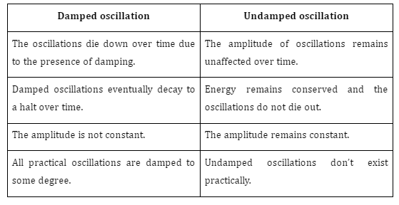
2. Differentiate between damped and undamped oscillation?
3. What are the applications of inductors?

Inductors find a wide range of applications, a few of which are:

  1. Choking, blocking, filtering, or smoothening high frequency noise.
  2. Used in oscillators.
  3. Used in power converters.
  4. Used in radios, TVs, wave generators, etc.

4. What are the differences between the capacitor and inductor?
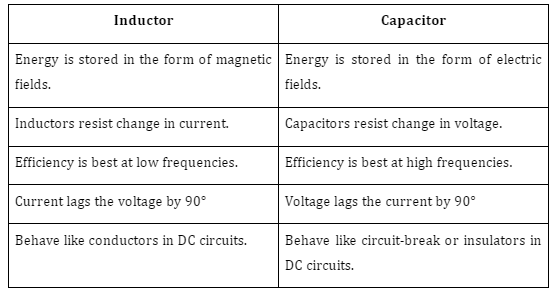
5. What are the uses of capacitors?

  1. Capacitors are used for quick release of electric charges. This is used in camera flashes, keyboards, etc.
  2. Capacitors can be used to detect high frequency electromagnetic radiation.
  3. Ignition systems use capacitors.
  4. Oscillators, amplifiers, and transmitters utilize capacitors.
AC Voltage Capacitor

Introduction

We know that a capacitor consists of two plates of conductors separated by an isolated distance and is also known as a dielectric. The capacitor limits or regulates the current when connected to an alternating current source, but it does not completely prevent charge drift. The capacitor gradually charges and discharges as the current reverses throughout each half-cycle. The highest charging current occurs while the capacitor’s plates are not charged, hence the charging process is not linear or instantaneous. Similar to the capacitor, once it is completely charged, its charge starts to drop dramatically. The capacity of a capacitor to hold a charge on its plates is known as capacitance. When a capacitor is connected to a voltage source in a DC circuit, current flows for the brief period of time required to charge the capacitor. The voltage across the conductive plates increases as charge accumulates on them, reducing the current. The circuit current zeroes out after the capacitor is fully charged.

Capacitance in AC circuits and capacitive reactance

A capacitor’s estimated capacity to store energy in an AC circuit is known as capacitance. The ratio of an electric charge to the corresponding difference in its electric potential is known as capacitance.

$$C=\frac{d Q}{d V}$$

Where dQ and dV are the charge and potential difference across capacitors, respectively. The capacitance may also be defined as the property of a capacitor to store the charge. The correlation between charging current (I) and the capacitors at which the capacitors supply voltage changes is given by 

$$I=C \frac{d Q}{d V}$$

Capacitive reactance

Capacitive reactance is the resistance to the flow of electricity through the AC capacitor. It is calculated in ohm and denoted by \(X_C\) and measured in the units of Ω. It is calculated mathematically using the provided formula.

$$X_C=\frac{1}{2 \pi f C}=\frac{1}{\omega C}$$

Where f is the frequency, C is the capacitance and ⍵=2πf.

The ratio of the effective current to the voltage across the capacitor is another way to describe the capacitive reactance. We get the conclusion that capacitive reactance is inversely linked to frequency from the aforementioned connection. This implies that a drop in frequency across the capacitor will result in a decrease in capacitive reactance, and vice versa.

Improving your Science concepts. Study Science Preparation for classes  6th, 7th, and 8th.

How does a capacitor work in AC?

The capacitor is directly linked to the AC supply in an AC circuit. The capacitor goes through a process of charging or discharging and blocks DC when an AC source is applied. The capacitor also partially obstructs the AC signal. Reactance is the term used to describe a capacitor’s properties in reaction to an AC signal. The capacitor has a short circuit in AC.

AC Capacitor Circuits?

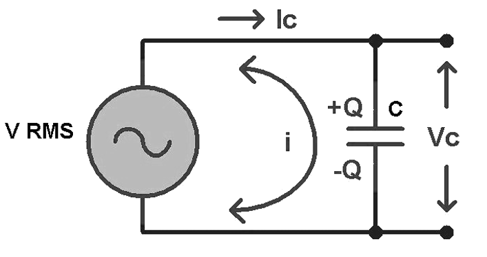
An AC capacitor circuit directly connects the AC supply to the capacitor to allow current to flow through the circuit. The capacitor’s plates are constantly being charged and discharged as a result of the AC supply.

Capacitor connected across a circuit.
An capacitor is connected to an ac circuit.

Role of capacitor in AC circuit

As long as there is a source, the capacitor will constantly charge and discharge. The time constant, however, governs whether it fully charges (transforms electrical energy into charge to store between two plates) or fully discharges (charges into electrical energy). We must use a load to charge a capacitor. The time constant is RC, where C is the capacitance and R is the load resistance of the circuit. The capacitor starts to charge when a power source is placed in its path. When fully charged, it will wait for the appropriate time to release the energy it has accumulated.

Role of capacitor in DC circuit

The capacitor starts to charge as soon as a DC supply is connected since DC sources have continuous voltage. Once fully charged, it will wait for the right time to release the charge it has saved. The outcome is that it is an open circuit after being fully charged. As a result, the capacitor acts as a component of an open circuit. The charge is continually charged and discharged with an alternating current, though, due to the variable voltage. The capacitor, therefore, performs the role of a resistor. In this instance, reactance is used in place of resistance, and a capacitor’s reactance is equal to

$$
\frac{1}{2 \pi f C} .
$$

The function of a capacitor in an AC circuit

Electrical circuits contain capacitors, which store electrical energy and raise the circuit’s power factor.

$$
\text { Power factor }=\frac{\text { Real Power }}{\text { Apparent Power }}
$$

AC through the capacitor (Derivation)

Suppose Q is the charge on the capacitor at a given time t, and the instantaneous voltage is V across the capacitor, then we can write,

$$
V=\frac{Q}{C}
$$

The voltage across the source and the capacitor is uniform. Then, according to Kirchhoff’s loop rule

$$
V=V_m \sin \omega t
$$

From the above two equations, we can write that,

$$
V_m \sin \omega t=\frac{Q}{C}
$$

Again,

$$
I=\frac{d Q}{d t}
$$

$$
I=\frac{d}{d t}\left(C V_m \sin (\omega t)\right)=\omega C V_m \cos (\omega t)
$$

Now, as we know,

$$
\begin{gathered}
\cos (\omega t)=\sin \left(\omega t+\frac{\pi}{2}\right) \\
I=I_m \sin \left(\omega t+\frac{\pi}{2}\right) \\
I_m=\frac{V_m}{\left(\frac{1}{\omega C}\right)}
\end{gathered}
$$

\(\frac{1}{2 \pi f C} \) is the capacitive reactance and is denoted by \(X_C\).

So,

$$
I_m=\frac{V_m}{X_C}
$$

Summary

The capacitor is an electrical part that creates a direct connection with the voltage of the source of alternating current. The capacitor alters its charge or discharge in response to a change in the supply voltage. With no real current travelling through the capacitor, the circuit’s current will first flow in one direction before switching to the other. In a circuit with direct current, things are different. The capacitor plate contains both positive and negative charges when current passes through it when it is linked to a direct current circuit. In many diverse sectors, including energy storage, filters, rectifiers, and other things, capacitors are used. Additionally, it is utilised in circuits to increase voltage and smooth out current swings.

Frequently Asked Questions

1. What is capacitive reactance?

Ans: The capacitive reactance in an electric circuit is the resistance that a capacitor presents to the flow of alternating current

2. State Kirchhoff’s voltage law.

Ans: The algebraic sum of potential differences and electromotive forces is zero in a closed loop.

3. State the role of the capacitor in the AC circuit.

Ans: The charge is continually charged and discharged in an AC circuit due to variable voltage. The capacitor, therefore, performs the role of a resistor. In this case, reactance is used in place of resistance, and a capacitor’s reactance is equal to \(\frac{1}{2 \pi f C} \).

4. State the role of the capacitor in the DC circuit.

Ans: The capacitor starts to charge as soon as a DC supply is connected because a DC source’s voltage is constant. Once fully charged, it will wait for the right time to release the charge it has saved. The outcome is that it is an open circuit after being fully charged. As a result, the capacitor acts as a component of an open circuit.

5. What is an electrolytic capacitor?

Ans: An electrolytic capacitor is a capacitor in which ion mobility makes conduction feasible. A liquid or gel with a high ion concentration is called an electrolyte.