Introduction
Ray diagrams allow us to ascertain the direction of the light as it moves to a certain location on an image of an item. In the Ray diagram, the incident and reflected rays are shown as lines with arrows. It also helps in determining the path of the light. Spherical mirrors are defined as having painted curved surfaces on one of its sides. Convex mirrors are spherical mirrors with painted inner surfaces, whilst concave mirrors are those with painted outward surfaces.
Representation of Images Formed by Spherical Mirrors Using Ray Diagrams
Ray diagrams may demonstrate how an image is created by tracing the routes taken by the incident and reflected light rays. They are designed in a way that allows each person to focus on a certain area of the object’s depiction. These ray diagrams rely on where the item is.
Check out online study options are a great way to clear the science concepts you need. Study Science Concepts for classes 6th, 7th, and 8th.
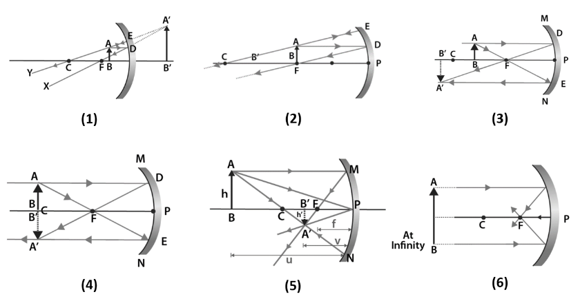
Rules for image formation of Spherical Mirror
- After reflection, a ray parallel to the main axis travels through the mirror’s focus.
- A ray that enters the primary focus after being reflected by the surface aligns with the primary axis.
- After reflection from the mirror surface, a light ray passing through the centre of curvature will reflect at a 180o angle.
- If a light beam is reflected at the mirror’s pole but is not parallel to the primary axis, it will obey the law of reflection.
These are all the above rules for obtaining an image formed by a concave mirror or convex mirror.
Table of image formation by a concave mirror
| Sr-no | Position of the object | Position of the image | Image Size | Nature of the Image |
| 1 | Between Pole and Focus | Behind the Mirror | Enlarged | Virtual and Erect |
| 2 | At Focus | At Infinity | Highly enlarged | Real and Inverted |
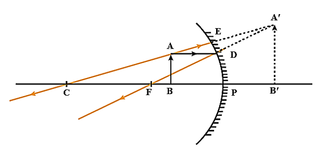
| 3 | Between Center of Curvature and Focus | Beyond Center of Curvature | Enlarged | Real and Inverted |
| 4 | At the Center of Curvature | At the centre of curvature | Same Size | Real and Inverted |
| 5 | Beyond Center of Curvature | Between Focus and centre of curvature | Diminished | Real and Inverted |
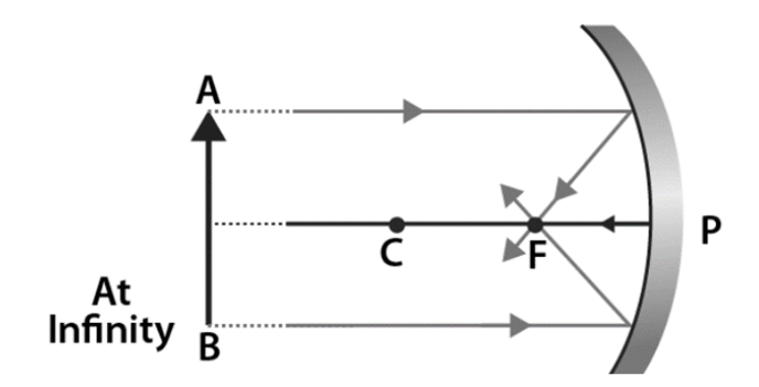
| 6 | Infinity | At the focus | Point size, Highly diminished | Real and Inverted |
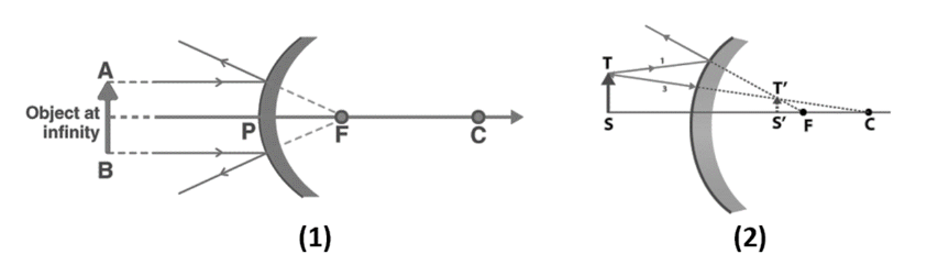
Ray diagram for Convex Mirror
Image formation by a convex mirror for different positions of the object.
| Sr. No. | Position of the object | Position of the image | Image Size | Nature of the Image |
| 1 | Between infinity and the pole | Between Pole and focus behind the mirror | Diminished | Virtual and erect |
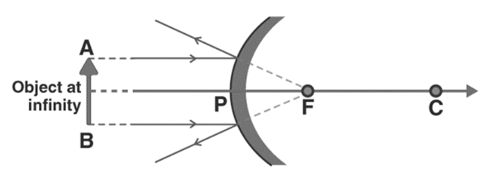
| 2 | Infinity | At focus behind the mirror | Point Size, Highly Diminished | Virtual and erect |
Mirror formula
The relationship between the object distance (u), image distance(v), and focal length (f) of the mirror.
1f=1v+1u
You can read more about Mirror Formula and different types of mirror in this article.
Summary
Ray diagrams are created when we use lines on paper or another flat surface to represent light rays and other rays. Understanding where and what kind of picture will develop is made easier with the aid of the Ray diagram of a spherical mirror. Hospitals, businesses, and other commercial settings often use these mirrors. It will be simple for us to analyse them now that we are aware of the two types of spherical mirrors and their applications regarding how the ray will behave after reflection.
Frequently Asked Questions (FAQs)
1. What is a Ray diagram?
Ans: Ray diagrams show the route travelled by light and what happens when it strikes a surface. In a ray diagram, each ray is represented as follows: a straight arrowhead pointing in the direction of the moving light. A ray diagram is a diagram that depicts the path that light takes to reach a certain location on an object’s image. On the diagram, rays represent the incident and reflected rays (lines with arrows).
2. How do you find out whether a mirror is concave or convex?
Ans: Spherical mirrors have a curved side painted on them. A mirror may be made by splitting a hollow spherical into pieces, painting the exterior, and using the interior as the reflecting surface. Concave mirrors are what these are. The outside of the hollow spherical becomes the reflecting surface if the object is painted from the inside. Convex mirrors are the name for this kind of mirror. Both mirrors serve different functions and provide different picture types.
3. What type of image is formed by concave and convex mirrors?
Ans: The light reflects off an object when it is placed in front of a mirror, creating a real or imagined image of it. When the light beams meet, a real image is created. Virtual pictures are produced when light beams from a point appear to diverge. A plane mirror can only ever generate a virtual image, but a spherical mirror can produce both virtual and real images. A concave mirror will create a real or virtual image. Virtual, upright images can only be reflected in a convex mirror. Depending on where it is placed, the concave mirror can provide an actual or virtual image. No matter where the item is, the convex mirror’s image is only a virtual and upright representation.


 Summary