Introduction
Everything in the universe exerts an attractive force on matter around it, which is where the concept of gravitational force comes in. Gravity is one of the four fundamental forces of nature, with the other three being strong nuclear force, weak nuclear force, and the electromagnetic force.
Strong nuclear force is a very short range force that is experienced by nucleons inside whereas charged particles interact via the electromagnetic interaction. Magnetic force is a part of electromagnetic force and we will discuss it here.
Magnet
A material that exerts magnetic force is termed as a magnet. Some elements possess this behaviour naturally, while others can get magnetised when brought inside a magnetic field. This phenomenon is referred to as magnetism and a large number of magnetic materials exist in nature.
Broadly, such materials are classified into three types, which include diamagnetic, paramagnetic, and ferromagnetic materials. At the same time, magnets themselves can be classified into the following:
- There are some materials which exhibit magnetic behaviour and retain magnetic properties over a long period of time. Common examples include iron, nickel, cobalt, etc. and these are classified as permanent magnets. Their magnetic properties are strong.
- Temporary magnets are materials with weak magnetic properties that cannot retain their magnetism. This includes soft iron or steel.
- Electromagnets are simply materials or circuits that develop a magnetic field when an electric current is passed through them.
The Bar Magnet
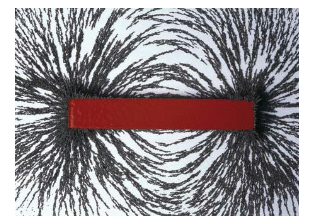
Naturally occurring magnets are irregularly shaped and do not have strong magnetic properties. Using specific ferromagnetic materials, we can construct strong magnets in the shape of a bar, which is what is known as a bar magnet.
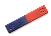
A bar magnet
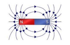
Field lines of bar magnets
All magnets have two poles, which are labelled as the south and north poles. One single pole of a magnet cannot exist and the poles are named south and north because of the direction they point if suspended freely. The magnetic field lines or lines of force originate at the north pole and form closed loops to the south pole. Inside the magnet, they go from south to north pole. The magnetic field is the property by virtue of which, a magnet can exert magnetic force on materials around it.
Types of Bar Magnet/ Rectangular Magnet
Bar magnets themselves are further divided into cylindrical and rectangular types. Generally speaking, when we refer to the bar of a material, we expect its length to be much higher than its width, which is true for all bar magnets. However, a bar magnet may also be shaped in the form of a cylinder, giving rise to a cylindrical magnet. This is formed by using a polished, curved surface instead of a rectangular one as in the case of a rectangular bar magnet.
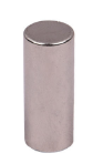
Cylindrical bar magnet
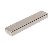
Rectangular bar magnet
Properties of Bar Magnet
- Like all magnets, bar magnets have a north and south pole, which exist even when the magnet is cut in half. We only end up with two magnets instead of one.
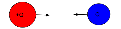
- Like all magnets, opposite poles of a bar magnet attract while similar poles repel.
- Bar magnets are designed from materials that can remain magnetised for a long period of time.
- They attract other ferromagnetic materials.
- The strength of a bar magnet is higher near the poles than at the centre.
Magnetic Field Lines
The strength and impact of a magnetic material may be determined pictorially via the magnetic field lines. The magnetic field is a vector quantity by virtue of which, magnets can exert magnetic force. Field lines are used to visually represent the magnetic field.
Properties of Magnetic Lines
- Magnetic field lines can never intersect.
- Field lines start go from north to south outside the magnet and vice versa inside.
- Magnetic field lines always form closed loops.
- The density of magnetic field lines represents the strength of the magnetic field.
Field lines of bar magnet
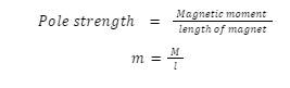
Pole Strength
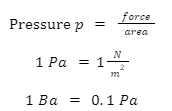
Pole strength, represented by m, represent the strength by which materials get attracted to a magnet. We can calculate the Magnetic moment M of a magnet by multiplying its pole strength with its length. The pole strength is measured in A m.
Alnico and Neodymium Bar magnet
Alnico Bar Magnet: Alnico magnets are created by combining Aluminum (Al), Nickel (Ni), and Cobalt (Co) to form a powerful magnet. These magnets are ideal for high-temperature applications and are sold under various names such as Alcomax, Hycomax, Alnico 5, and Alnico 8. They are highly resistant to corrosion and can be cast into complex shapes and larger sizes and at the same time, they prove cost effective as well.
Neodymium Bar magnet: A neodymium bar magnet, also known as a rare earth magnet, has a powerful magnetic field and is available in various sizes. It is composed of neodymium (Nd), iron (Fe), boron (B), and varying amounts of dysprosium and praseodymium. This type of magnet is the strongest of all known magnetic materials. However, it is best suited for use in low-temperature environments and requires a coating to prevent corrosion. Due to the expensive cost of its raw materials, neodymium bar magnets are highly expensive.
Summary
Magnets are materials that have the ability to attract iron, steel, and other such materials towards themselves. One type of magnet is the bar magnet, which is shaped like a bar and is comparatively stronger than naturally occuring magnets. Today, Alnico and Neodymium magnets are two of the strongest permanent magnets used in different settings and a large number of other magnets have also been created for use in various types of situations.
Frequently Asked Questions
1. What is the need for horseshoe-type magnets?
A horseshoe magnet is designed in the shape of a U, which makes it more powerful than other magnets due to the concentration of magnetic field lines at its poles. Because the two poles of a horseshoe magnet are aligned in the same direction, their strength is significantly stronger than other magnets. This makes them suitable for lifting heavy objects.
2. Why do the same poles repel each other and different poles attract each other?
This is a natural property of magnets that may be understood by their field lines. Field lines originate at the north pole and end at the south pole. Thus, when similar poles are brought together, the tendency to form closed loops is disturbed, which results in repulsion.
3. Our earth is like a bar magnet. Explain.
Our Earth behaves like a bar magnet whose field extends thousands of kilometres into space, though it is not very strong.
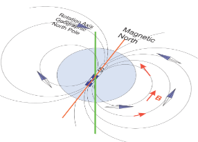
Earth as a bar magnet
This magnetism is developed in the earth’s core due to the convection current of molten iron and nickel. These particles are charged and thus, constitute a magnetic field
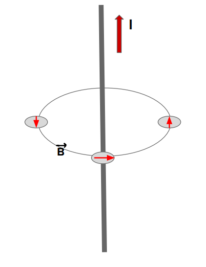
4. State right-hand thumb rule.
The right-hand thumb rule can help us obtain the direction of a magnetic field caused by a current-carrying wire. If we align our thumb along the direction of flow of current, then our fingers curl in the direction of the magnetic field.
5. What are electromagnets?
Electromagnets are created by passing a current through certain current elements like coils or wires. They only remain magnetized as long as the current flows and their strength depends upon the current passed.


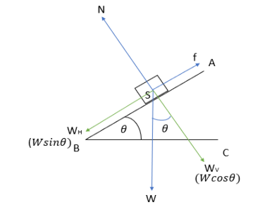
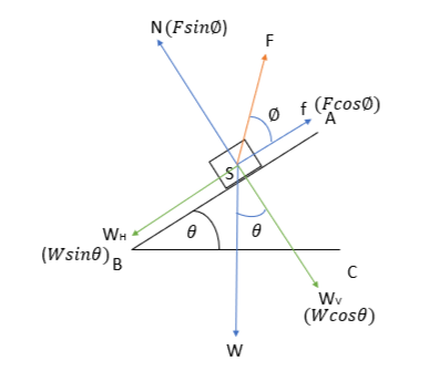
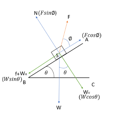
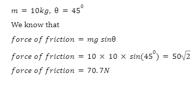
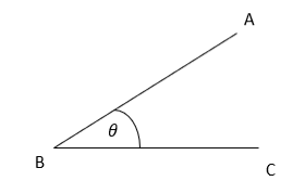 Inclined plane AB
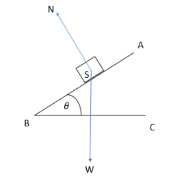

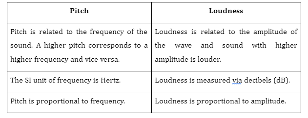 2. Are pitch and frequency different?