Layers of the Earth

Introduction

Astrophysics deals with the knowledge of the universe beyond this Earth. It explores the processes that occur in the depths of space and astrophysicists also study the physics of the various planets and stars in and beyond and the solar system.

Closer to home, we have a field of science known as geology, which is the study of the Earth’s physical structure and substance. Our knowledge of what lies inside the Earth as well as various phenomena that occur due to changes within this composition is all classified under geology. In this article, we are going to explore what the Earth is made out of and how its composition is classified.

What is Earth?

Earth is the third planet in our solar system and the fifth largest by size. It is a terrestrial planet, meaning that it is mostly made up of solid, rocky materials. The surface of Earth isn’t smooth. Rather, it is covered in mountains and valleys in some portions while water covers the remaining 70 percent of its surface, earning it the nickname “ocean planet” and giving it the ability to support life. Its atmosphere is mostly composed of nitrogen and oxygen and a strong magnetic field around the planet prevents it from the effects of solar radiation. Each day on Earth lasts 24 hours and each year comprises 365.25 days. Interestingly, Earth is the only planet in the solar system that has exactly one natural satellite: the moon.

Earth’s Magnetic Field

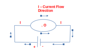
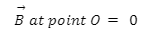
The intrinsic, natural magnetic field of the Earth arises due to the convection currents developed inside the core of the Earth and extends all the way into space. It gives rise to a layer of the atmosphere known as magnetosphere and is also known as geomagnetic field.

layers of earth

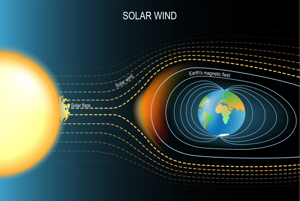
Earth’s magnetic field.

Convection currents in the core develop due to the flow of molten materials like iron inside the core of the Earth. Since these materials contain charged particles, their motion gives rise to a current which creates the magnetic field of the Earth. Due to this field, the Earth can also be thought of as a bar magnet, though its poles do not coincide with the geographical poles.

Layers of Earth

The physical composition of Earth is classified into the crust, the mantle, the outer core, and the inner core. The following figure depicts this classification and we will discuss each layer in detail.
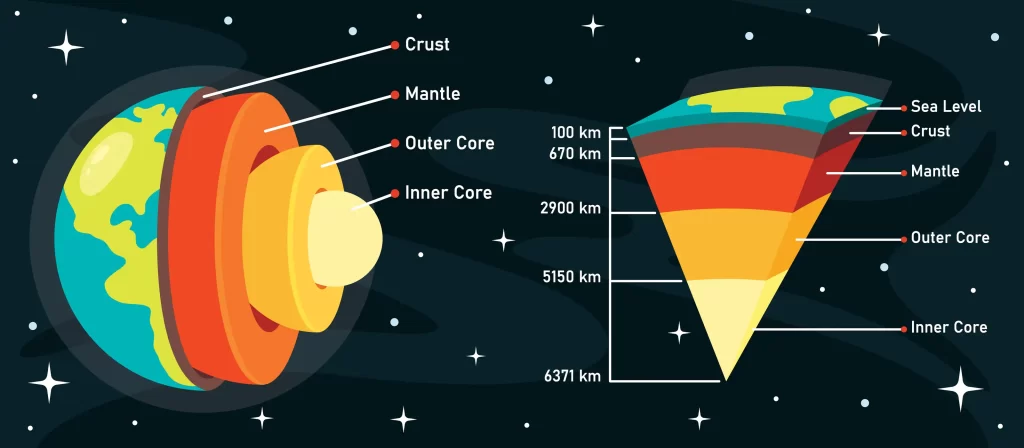
Layers of the Earth

Inner core

  • The core is the deepest and hottest layer of the Earth and it lies at the very center.
  • It is composed of solid metals like iron, nickel and trace amounts of gold, cobalt, and platinum.
  • The inner core has a temperature of around 5,200 ℃.
  • Due to the enormous pressure, the core remains solid despite the temperature far exceeding its contents’ melting points.
  • The inner core is approximately 1220 km in radius.
  • The lighter elements are present near the top of the core while the heavier elements tend to shift downwards. This process is an exothermic one and it heats up the planet.

Outer core

  • The outer core lies above the inner core and is the only layer containing iron, nickel, and other substances in a liquid state.
  • Its temperature is around 4000-9000 ℉. 
  • The rotation of the Earth creates a convection current in this layer, forming a magnetic field.
  • The outer core is about 2200 km thick and carries 15% of the Earth’s volume.
  • Its density is approximately 9.5 to 14.5 g/cc.
  • The point of discontinuity between the core and mantle is known as Guttenberg’s discontinuity while the inner and outer cores are separated by Lehmann discontinuity.

Mantle

  • The mantle is the solid layer beyond the core and is about 2900 km thick.
  • It occupies 84% of the Earth’s volume and is made of elements like silicon and magnesium.
  • Its density is in the 3 to 5 g/cc range. The mantle is in a solid state.
  • Its upper and lower portions are separated by the Repitti discontinuity. 

Crust

  • The crust is the outermost, solid layer of the Earth upon which we live. Its thickness varies greatly from 5 to 40 km.
  • Most of the crust is covered in water and in oceanic regions, the crust is only 5-10 km thick.
  • The crust occupies a meager 1% of Earth’s total volume and it forms the lithosphere of the Earth.
  • The outer crust contains sedimentary rocks made up of silicon and aluminum and has a density of around 3 g/cc.

Summary

So far, Earth is the only known planet that supports life. It lies third in our solar system and carries its own magnetic field to prevent it from solar winds. The study of the physical structure and substance of Earth is known as geology and in this article, we explored the various layers that make up this planet. These included the crust, the mantle, and the core.

Frequently asked questions

1. What is hydrostatic equilibrium?

Hydrostatic equilibrium refers to the balance between the gravitational force and the pressure of a gas or liquid. It is a self-regulating force. 

2. What is the percentage of fresh water on the Earth? 

While about 70% of the Earth’s surface is covered in water, only a small 3% of it is fresh and out of this 3%, 1% is in the form of icecaps and glaciers. The remaining 2% is what we use for our daily activities. 

3. What are the conditions necessary for the geodynamo process?

The Earth can create its own magnetic field given that:

  1. It is rotating at a sufficient velocity.
  2. Its core contains conductors in a liquid state.
  3. There is enough internal energy to create the convection current.

4. What elements are present in the inner core?

The inner core is mainly made up of iron (around 80%). About 5 to 15% of it is nickel, 2 to 3% is siderophiles, and the remaining 5 to 10% is sulfur and oxygen. 

5. Why is the core so incredibly hot?

The heat provided during the formation of the Earth, along with the heat generated due to friction and radioactive decay of elements makes the Earth’s core immensely hot.

LC Oscillations

Introduction

Electronics is a branch of physics that focuses on the behavior of electrons in electronic circuits. Unlike classical electrical engineering, electronics employ active devices as components. Note that active devices are devices that can control the flow of electricity in a circuit. On the other hand, passive components only consume electricity but cannot regulate it. Vacuum tubes which have the ability to control the flow of electrons, were initially fundamental to electronics but that technology is now obsolete. Today, you can create much more intricate circuits in much smaller form factors using transistors. 

An electric circuit is a closed path through which electric current can flow. Electrical components such as transistors, resistors, capacitors, and inductors are utilized in these circuits. Electronic devices, including computers, are constructed from thousands of electric circuits composed of these electronic components.

What is oscillation?

You have already come across hundreds of oscillations in your daily life. The term “oscillation” refers to the repetitive to and fro motion of a device or quantity. When a particle oscillates, it vibrates about an equilibrium position periodically. Common examples of oscillation you might be familiar with include the pendulum of a clock, your heartbeat, and the movement of strings in musical instruments. The pendulum moves to and fro from its mean position. Similarly, in a slinky, the spring extends and contracts rhythmically. An oscillation can be represented using a sine wave, whose value itself oscillates about 0. Oscillations can be free, damped, or forced.

Inductor

An inductor is a passive electronic component that converts electrical energy into magnetic energy and stores it. It is made up of a coil of wire that is generally wrapped around a given core but can be made without a core as well. An inductor works on the principle of electromagnetic induction, which is related to the generation of a magnetic field due to a changing current. 

Since an inductor is in the form of a coil, when current going through it changes, the loops of the coil resist the corresponding change in magnetic field. A quantity that characterizes inductors is the inductance. It is defined as the ratio of induced EMF to the change in current over time. The figure below shows a few common inductor types:

LC Oscillations

Inductor types

The increase in current creates a magnetic field in the inductor. This magnetic field reduces when the current through it decreases and the energy stored in the magnetic field is converted into electrical energy. Thus, an inductor can store energy in the form of a magnetic field.

Capacitor

Capacitance is the ability to store electric charge and capacitors are devices that facilitate this. Generally, they are made of two conducting plates separated either by air or by some other dielectric material like ceramics, plastics, mica, etc. 

When a capacitor is connected to a DC source, electrons move from the negative terminal and accumulate on the conducting plate, inducing a positive charge on the other plate. The dielectric material in between the plates prevents electrons from crossing the barrier. This way, electrons get stored on the plates and the energy thus stored can be utilized later. Mathematically, capacitance is measured using the following formula:

The following diagram shows a capacitor:

Capacitor

LC oscillator

An LC circuit is so named because it contains an inductor and a capacitor. Capacitance is depicted by C while inductance is depicted by L, hence the name LC circuit. An LC circuit is also sometimes referred to as a tank circuit. An LC circuit can act as a resonator that stores energy and then oscillates at a particular frequency using positive feedback without external influence.

LC Oscillator

Working of LC oscillator

  1. In the circuit depicted in the figure above, we have an inductor and capacitor connected in series.
  2. When voltage is applied, the capacitor starts developing a charge. In this time period, the inductor does not receive anything.
  3. When the applied voltage is removed, the energy stored in the capacitor flows to the inductor and the capacitor discharges.
  4. Once the capacitor has been completely depleted, the inductor carries all the energy and it removes it into the circuit. This charges the capacitor in the opposite direction till all energy is transferred to it.
  5. This cycle repeats to give rise to LC oscillations.

Applications

LC oscillators find a wide range of applications in electrical circuits. Here are a few examples.

  1. They are used in AC-DC converters.
  2. They are used in amplification circuits.
  3. Radios, TVs, transmitters, filters, etc. all utilize LC circuits.
  4. They are used for induction heating.
  5. They are used in sine wave generators.

Summary

Capacitors store charge while inductors store magnetic energy. When connected in series, they can be used to create oscillator circuits which do not require external influence to operate. This article discussed concepts related to LC oscillator circuits in detail.


Frequently asked questions

1. What are free and forced oscillations?

Free oscillations occur when an oscillating body is allowed to oscillate without external influence. On the other hand, one can force a body to oscillate continuously using an external force, which is known as forced oscillations.

2. Differentiate between damped and undamped oscillation?

3. What are the applications of inductors?

Inductors find a wide range of applications, a few of which are:

  1. Choking, blocking, filtering, or smoothening high frequency noise.
  2. Used in oscillators.
  3. Used in power converters.
  4. Used in radios, TVs, wave generators, etc.

4. What are the differences between the capacitor and inductor?

5. What are the uses of capacitors?

  1. Capacitors are used for quick release of electric charges. This is used in camera flashes, keyboards, etc.
  2. Capacitors can be used to detect high frequency electromagnetic radiation.
  3. Ignition systems use capacitors.
  4. Oscillators, amplifiers, and transmitters utilize capacitors.

Measurement of Speed

Introduction

In physics, there are two types of physical quantities: those that contain a direction as well as magnitude and those that contain only direction. The former are known as vector quantities and the latter are known as scalars. Time, temperature, mass, etc. are scalar quantities since there is no physical sense for mass to have direction. On the other hand, velocity, acceleration, force, etc. are quantities whose directions are important and thus, are examples of vectors.

The process of determining the magnitude and where applicable, the direction of a quantity is known as measurement. It yields a numerical value along with a direction if required. Measuring quantities also requires a standard set of units with reference to which, we can give their numerical value. For instance, we know our height to be 160 cm only because we have a reference value for how long 1 cm is. For this end, the SI system of units was developed to provide a global standard.

What is speed?

Speed measures the pace at which an object moves with reference to a reference point. When we talk of speed in physics, we are concerned with only the distance covered and do not inquire about the direction. Thus, speed is a scalar quantity. Mathematically, we can write:

In the SI system of units, speed is measured in m/s whereas the cgs system measures it in cm/s. Other common units include km/h, mph, etc.

Apart from moving in a straight path, objects can also move along a circular path in which case, we can measure their angular speed in terms of the angle they sweep out in a given time interval. Mathematically,

Types of speed

Physicists classify speed into various types depending on different criteria. Here are a few common classifications:

Uniform speed

An object is said to possess uniform speed if the speed remains constant in time. That is, even as time passes, its speed does not change.

Variable speed

Objects whose speed is not constant in time are said to be moving with a variable speed.

Average speed

We know that it is practically difficult for objects to keep moving at exactly the same speed over time. But over the course of a journey, one can calculate an average speed which gives us a general idea about the motion of the object. 

Average speed is measured by taking the total distance that the object covered and dividing it by the total time it took to cover that distance. That is,

Instantaneous speed:

As previously mentioned, an object may have different speeds at different instants in time. The value of its speed at an exactly defined moment in time is termed as its instantaneous speed at that moment.

The calculation for speed

To calculate an object’s speed, we can simply apply the formula for speed. Thus,

A few common examples of speeds measured by scientists include the speed of light in vacuum, which is approximately 3E8 m/s. On the other hand, the speed at which Earth rotates about its axis is 7.28E-5 rad/s and the speed at which it travels around the sun is given as 30 km/s.

Relation between angular speed and linear speed

We can derive a relation between the angular and linear speeds of an object. We know that linear speed is 

Further, we know that for circular motion, when the angle swept is very small, the arc length can be approximated as 

The angular speed is written as ⍵=θ/t. Hence, if we multiply both sides of this equation with r, we get:

Thus, angular and linear speeds are related by the equation v=r.

Solved examples

1. Raju drives at 15 km/h for 3 hours. How much distance did he cover?

We know that 

2. If the blade of a fan rotates at an angular speed of 16π rad/sec, what is the time taken for one complete rotation.

Angular speed can be directly related to the time taken for one complete rotation (T) as follows:

Hence, the fan completes one rotation in 0.125 seconds.

Summary

Speed is a scalar quantity that measures the pace at which an object is moving. It is measured by dividing the distance covered by the time taken to cover that distance. Angular and linear speeds can be related to each other.

Frequently asked questions

1. Describe Newton’s first law of motion.

Newton’s first law states that if an object is moving or at rest, it will continue in that state unless some external factor forces it to change its state of motion. Unless some external factor stops a ball from rolling, it will continue rolling.

2. How does the angular speed of an object remain the same at all points?

Angular speed measures the rate at which a certain amount of angle is swept by an object. It changes with radius and thus, remains the same for all points.

3. How does an ice skater control their angular speed?

Since angular speed depends on the radius, if the ice skater or ballet dancer pulls in their arm close to their body, they speed up. They can also reduce their speed by extending their arms. This is related to the law of conservation of angular momentum.

4. What instrument measures linear and angular speeds?

Linear speed is measured by speedometer in a car while angular speed is measured by an instrument known as tachometer.

5. What is the difference between speed and velocity?

Joule’s Law

Introduction

In physics, we measure energy and work in units of Joule, one unit of which is equal to applying 1 Newton of force over a distance of 1 meter. In various objects, applying force or stress leads to the object heating up and the amount of heat produced is equal to the work done. On the other hand, in electrical circuits, it is the flow of current that leads to the generation of heat. The amount of heat generated in electrical circuits is directly proportional to the square of the current passing through them, the resistance of the circuit, and the time for which the current is made to flow. This relation is known as Joule’s law of heating. This article focuses on this law and discusses its concepts and applications.

What is Joule? 

Joule is a unit of measurement for both energy and work. It is defined as the work done by applying a force of one newton over a distance of one meter. When this occurs, one joule of energy is produced. Joule is equivalent to Newton meters. It is important to note that every time mechanical force is applied, an exact equivalent of heat is generated.

Joule’s law of heating

Joule’s law relates the heat generated in an electrical circuit to current, resistance, and time. It states that the heat generated in an electrical component varies directly with the square of the current, the resistance of the circuit, and the duration for which current flows in the equation. Mathematically,

James Joule discovered the equation for power dissipated by a resistor through empirical observation of power, current, and resistance measurements. He found that the power dissipated by a resistor is proportional to the square of the current passing through it. This process is known as Joule heating, where electrical energy is converted into heat by a resistance element. This theory applies to any electrical device designed to generate heat, such as electric heaters and toasters. Joule’s law and Ohm’s law were both discovered empirically by examining real-world data.

The dissipation of power in an electrical circuit simply means that due to the current flow, some power is lost in the form of heat. According to the law of conservation of energy, energy cannot vanish into nothingness. Instead, it is lost to the surroundings. This concept is also used in toasters and heaters. They contain heating elements which have a high wattage and thus, generate enormous amounts of heat. That heat is then radiated to the environment, heating up the room. 

We can derive Joule’s law as follows:

Using this formula, we have:

Joule heating power equation for AC and DC

The equation we have derived for calculating the heat generated in an electrical circuit is equally valid across AC and DC components. Thus, regardless of the nature of current, the heat generated is given by:

However, while dealing with AC components, the value of current becomes dependent on time.

Application of joule’s law of heating

  1. Electric fuse

An electric fuse is a small piece of wire that is generally manufactured from a tin alloy and has a specific melting point. It is connected to electrical appliances in series and protects them from damage due to high current.

Joule's Law

Electric fuse

When the current passing through the circuit crosses a threshold, the heat generated in the circuit increases the temperature of the fuse wire, which melts and thus, the connection is broken. Thus, the appliance remains safe. There are other applications of Joule’s law as well, which include:

  • Electric heater
  • Electric iron
  • Electric geyser

Summary

Energy and work are measured in units of Joule. 1 J of work is done when an object is made to move a distance of 1 m by applying a force of 1 N. Joule is equivalent to Newton meters.

In electrical circuits, the flow of current leads to the generation of heat, which is related directly to the square of the current, the resistance, and time. This is known as Joule’s law of heating and in this article, we discussed this concept in detail.

Frequently Asked Questions

1. What are the variables that affect heat in a circuit?

As per Joule’s law, heat in a circuit depends on current, resistance, and time.

2. Which device doesn’t follow Joule’s law?

All electric circuits follow Joule’s law. However, in a number of situations, heat generation is an undesired side effect which must be minimized. On the other hand, devices like geysers and irons actually need heat generation.

3. Is the effect of joules heating reversible?

The heat energy dissipated in circuits can not be brought back by reversing the direction of current. That energy is lost to the environment.

4. Do ideal conductors also suffer from heating?

In theory, no. An ideal conductor is one whose resistance is zero and thus, the heat generated in an ideal conductor would be zero.

5. Does voltage change affect heat?

Yes. Changing the voltage applied to a circuit changes the current flowing across it and thus, the amount of heat generated changes.

Acceleration Time Graph

Introduction

Acceleration is a physical quantity that describes change in velocity over a given time interval. It is a vector quantity with both magnitude and direction, and is measured in metres per second squared (\(m/{s^2}\)). Acceleration can be thought of as the derivative of velocity or the second derivative of position.

An object moving at a constant velocity has zero acceleration. Thus, acceleration occurs when an object changes its speed or direction, and it is a measure of an object’s ability to reach a given speed.

There are two types of acceleration: average and instantaneous. Graphs, such as velocity-time, position-time, and acceleration-time graphs, can be used to mathematically represent the motion of an object and develop a better understanding of its motion.

What is the Acceleration-Time Graph?

The acceleration-time graph is a pictorial representation of an object’s motion wherein, time is taken on the X-axis as the primary variable, and acceleration is represented on the Y-axis as a function of time.

The area of this graph gives velocity, whereas its slope leads us to a physical quantity that is known as jerk.

Acceleration-Time Graph Explanation

Since the acceleration in such graphs is shown as a function of time, they can be used to understand how an object’s acceleration varies over time. If the graph is going down with time, it means the object is losing acceleration.

When an object undergoes negative or reverse acceleration, it is said to experience retardation.

Special cases in acceleration-time graph

  • When particle moving with constant acceleration: If the acceleration of a particle is a constant given by at time , which does not change with time, it will be represented by a horizontal line in the graph.

Uniform acceleration

  • When a particle is moving with increasing acceleration at constant rate: Acceleration that is increasing at a constant rate will be shown by a straight line making an acute angle with the x-axis or the horizontal.

Increasing acceleration

  • When a particle is moving with decreasing acceleration at constant rate: If the acceleration is decreasing at a constant rate, it is bound to reach zero after a given time interval. Thus, such a graph is a straight line making an obtuse angle with the x-axis.

Decreasing acceleration

Vertical Axis

The acceleration of an object is displayed on the Y-axis of a graph, with time on the X-axis. This allows us to see how acceleration changes with respect to time.

Acceleration-time graph

Slope of the Acceleration Graph

Given a graph, we can calculate its slope, which would allow us to measure its steepness. For an acceleration-time graph, the slope represents the change in acceleration over time, which is known as jerk. In mathematical terms, it is the third derivative of the position vector. The sensation of jerk is experienced when there is a change in acceleration with respect to time.

\(\begin{array}{l}Slope = \frac{{\Delta y}}{{\Delta x}}\\jerk = \frac{{Change\;in\;acceleration}}{{change\;in\;time}}\end{array}\)

Acceleration-time graph

Jerk: Jerk is the rate of change of acceleration. The derived unit of jerk is


Thus, its unit is \(m/{s^3}\).

The dimension of jerk:


Example of jerk: Suppose a car is in motion with a given acceleration and the driver suddenly notices a speed bump. He will slow down rapidly and thus, the car’s acceleration changes abruptly in a short period of time. This sudden change in acceleration creates a jerky motion for objects inside the car, which is an example of jerk in action.

Area Under the Acceleration Graph

When we calculate the area under an acceleration-time graph, we arrive at the object’s velocity. This is easy to prove since area of a curve is given by xy.

Velocity: Velocity represents the time rate of change of an object’s displacement.

\(Velocity = \frac{{displacement}}{{time}}\)

Its SI unit is  and dimension is \(\left[ {L{T^{ – 1}}} \right]\).

Important Things To Remember In Acceleration Time Graph

  • The slope of an acceleration-time graph gives us jerk.
  • Two objects have coinciding acceleration-time curves when their accelerations are the same.
  • Motion with constant acceleration would yield a straight line curve with zero slope, i.e., the line would be horizontal.

Acceleration Graph Solved Example

Example 1: Using the given graph, find velocity.

Acceleration-time graph

Solution: We can see that in the curve,

\(\begin{array}{l}a = m/{s^2}\\t = 4s\end{array}\)

Area under the curve will give us the velocity of the object.

\(\begin{array}{l}Velocity = acceleration \times time\\v = 15m/{s^2} \times 4s\\v = 60m/s\end{array}\)

Hence the velocity of the object is .

Example 2: If the acceleration of a car is given as , find the jerk at time .

Solution: We are given that

Since jerk is the first order derivative of acceleration. Thus,

Therefore, the jerk experienced the car is 40 \(m/{s^3}\) in the x-direction.

Summary

In a graph showing the variation of acceleration with time, time is represented on the x-axis and acceleration on the y-axis. This is because time is a primary and independent quantity whereas acceleration depends on time.

The slope of the acceleration-time graph represents the rate of change of acceleration, commonly known as jerk. Jerk is felt by the body when there is a sudden change in acceleration with respect to time and can be calculated as the third order derivative of the position vector. Just like acceleration, jerk is a vector quantity with both magnitude and direction.

Frequently Asked Questions

1.How can we find the jerk from the acceleration-time graph?

Jerk is the slope of the acceleration-time graph and can be calculated thus.

2. How can we find velocity from the acceleration-time graph?

If we wish to find velocity, all we need to do is calculate the area under the curve.

3. What is the use of an acceleration-time graph?

The graph helps us pictorially represent an object’s motion and calculate associated quantities of motion.

4. What is the relation between jerk and position vector?

Jerk is the third order derivative of the position vector.

Difference Between Conduction Convection and Radiation

Introduction

Heat in an object does not remain stationary and tends to move from high-temperature to low-temperature areas. Thus, overheated materials tend to cool down while cold materials tend to absorb heat from the environment and warm up. Similarly, when two objects at different temperatures come into contact, heat energy is transferred from the hotter object to the cooler one. You might have seen dogs sticking out their tongues while panting. This helps them cool down because when they inhale, moisture in the air condenses on their tongues, forming liquid droplets that later evaporate. This evaporation requires thermal energy, which is supplied by their tongues, aiding them in cooling down.

Evaporation

Dogs cool themselves

What is conduction?

Conduction refers to the transfer of heat, electricity, or energy between particles of a substance without movement of the particles across regions of different temperatures themselves. It occurs in solids, liquids, and gases, and is the primary source of heat transfer inside solids. Since the atoms inside metals are placed close together, they conduct electricity well. Physically, conduction occurs by vibration. When a solid object is heated, its atoms/molecules start vibrating rapidly. However, since each atom or molecule is bonded to the next one, this vibration causes the neighbouring atoms to vibrate, and the process continues till the heat energy has spread across the whole solid.

Mode of conduction

Conduction occurs when there is a difference in temperatures across different portions of a material. Metals conduct heat very well whereas, liquids and solids tend to make bad conductors of heat. Furthermore, heat conduction is better when the surface area of the solid is large.

Thermal Conductivity

Thermal conductivity measures an object’s ability to transmit heat. It refers to the rate of heat transfer per unit time between the two ends of an object, given a specific cross-sectional area. We know that heat always flows from a higher temperature region to a lower temperature region. Suppose we were given a uniform shaft with length ‘l’ and cross-sectional area A. If the temperature at the two ends of the shaft were ,

, and Q amount of heat was transferred through the shaft, then it is natural that Q would be proportional to the temperature difference, the cross-sectional area, and the time taken for the conduction to occur. Further, it would be inversely proportional to the length of the shaft. Hence, we can say that

Here, K is the constant of proportionality known as the thermal conductivity.

What is convection?

Convection refers to the transfer of heat by the movement of particles in a medium from the hotter region to the colder region. It is a common way of heat transfer in liquids and gases. For instance, in a hot air balloon, the air molecules at the bottom of the balloon heat up and rise, creating low-density hot air that fills the balloon and causes it to ascend. Meanwhile, the cold air at the top of the balloon moves downward as the hot air rises, thus creating a continuous cycle of air movement.

Hot air balloons 

Mode of Convection

  1. Chimneys are placed above stoves since hot molecules from our cooking will rise up and reach it via convection.
  2. Land and sea breeze flow based on convection. The land gets warmer faster than the sea, causing air molecules above it to rise up. The cool air from the sea flows in to maintain a pressure balance. The reverse process occurs at night.

What is radiation

Radiation is the transfer of heat without the need for particles or a medium to carry it. For instance, thermal radiation is how the sun transfers heat to the earth. During the process of radiation, heat is emitted from hot objects in all directions and unlike conduction and convection, radiation can take place even in a vacuum since it doesn’t require any a medium. Radiation of heat occurs in the form of electromagnetic radiation. Hot objects emit radiation in all directions, which is responsible for carrying heat and allows the heat energy to reach different places without the need of a medium.

Examples of conduction, convection, and radiation

  1. Metals are excellent conductors of heat, which makes them perfect for cooking. On the other hand, since wool is a bad conductor, we use it in our sweaters, which keeps the heat in.
  2. Thermometers utilise mercury, which is also an excellent conductor.
  3. Hot air balloons use the process of convection to function as described earlier.
  4. We are advised to use bright colours in summers since they reflect the heat energy coming to us in the form of radiation. Similarly, aircrafts are made up of bright colours so that they reflect whatever heat energy is incident on them.

Summary

Heat can be transferred between objects of different temperatures through convection, conduction, and radiation. Conduction occurs in solids while convection occurs in liquids and gases. Radiation can occur without the need for a medium. An example of convection is that of sea breeze and land breeze. During the day, land surfaces become warmer than seawater, causing the hot air to rise and cooler air to move towards the land at night. Temperature can be measured using Fahrenheit, Celsius, and Kelvin scales. The amount of heat energy in an object depends on the material’s mass, the temperature difference, and the material’s properties.


Frequently Asked Questions

1. What is Widemann-Franz Law?

This law states that the thermal and electrical conductivities of metals are directly proportional to their temperature, and at a specific temperature, they are equal.

2. What is Black body radiation?

A black body is a material that absorbs all radiation incident upon it. When held at a constant temperature, it emits all of the absorbed energy. The emitted radiation is independent of the material’s properties and is called black body radiation and it is emitted uniformly in all directions.

3. What is Stefan-Boltzmann law?

This law states that the heat energy emitted from a perfectly black body is proportional to the fourth power of temperature.

4. What happens when an ice cube is placed in water?

The process of conduction takes place when an ice cube is immersed in water. Heat from the water flows into the ice cube and melts it.
5. Discuss cooling via evaporation

Evaporation is a process wherein a liquid substance absorbs heat and changes into a gaseous state. Since heat energy is required for this to occur, evaporation can take away excess heat from objects and cool them down.


Difference Between Concave and Convex Lens

Introduction

Reflection is a phenomenon wherein, when a wave hits a surface, it does not get absorbed. Instead, the incident energy is sent back from the surface. Metal surfaces can reflect as much as 80-90% of the light when highly polished and most commonly, mirrors are made using a silver coating that is deposited on the backside of the glass. The Hale Telescope located atop Mount Palomar in California is the world’s most reflective surface.

lead magnet

Similarly, refraction occurs when a wave crosses from one medium to another, which changes its direction and speed. One of the most commonly used optical devices is a lens, which is formed by the intersection of two spherical surfaces.

What is a lens?

A lens is one of the most commonly used optical devices made up of two intersecting spherical surfaces. The lens is said to be thin when the distances between the surfaces become small and it is not necessary for both of the surfaces to be spherical. In fact, one of them can be a plane as well. The line joining the centre of the two surfaces is known as the principal axis and the plane through this axis is known as the principal section of the lens. A point that lies on the principal section is known as the optical centre.

There are two types of lenses: Converging lenses, and diverging lenses.

Types of lens

Difference between Lens and Mirror

What is the concave lens? 

A concave lens is a type of lens that diverges a straight light beam, creating a virtual image that is smaller than the object itself. Both sides of the concave lens are curved inwards, giving it a concave shape. Due to this shape, these lenses are also known as diverging lenses as they cause light rays to spread out. For instance, when a ray coming from the sun falls on a concave lens parallel to the principal axis, it appears to emanate from a point on the principal axis known as the primary focal point of the lens.

Similarly, when a parallel ray is emitted from the opposite side of the lens, it will also appear to converge to the primary focal point, typically denoted by the letter ‘F’. Further, a light beam originating from the focal point will become parallel to the principal axis after passing through the lens.

Lens formula for concave lens

The lens formula is an equation applicable to all types of lenses and relates the distance of the object (u), the image distance (v), and the focal length of the lens. In the form given below, it is valid only for a thin lens but formulae for thick lenses have also been derived:

What is the convex lens?

A convex lens protrudes outwards on both sides and is thicker in the centre and thinner at the edges. It is called convex because it concentrates the light falling on it. When a light beam parallel to the primary axis falls on the lens, it passes through the primary focal point on the other side. Similarly, when a light beam originates from the primary focal point and hits the lens, it emerges parallel to the principal axis. 

One common example of the effects of this lens may be seen when it is held towards the sun and sunlight is focused on a piece of paper. The sharp, radiant image of the sun obtained this way is bright and has concentrated all the light rays in one point. This concentration is strong enough to burn the paper and the images formed this way are called real images.

lead magnet

Lens formula for convex lens

The lens formula for convex lenses is the same as that for concave lenses. That is,

Uses of convex and concave lens

Convex Lens

  1. Convex lenses are used to manufacture magnifying glasses. 
  2. Microscopes utilise convex lenses.
  3. People suffering from hypermetropia are prescribed convex lenses, which can help focus the image correctly on the retina.
  4. Convex lenses are also used in cameras.

Concave lens

  1. Just like hypermetropia, myopia is corrected by using concave lenses.
  2. Flashlights, binoculars, telescopes, eyeglasses, etc. are common devices that use concave lenses. 

Summary

A lens is a translucent medium formed by the intersection of two spherical surfaces or a spherical and a plane surface. When the surfaces are close, a thin lens is formed. There are two types of lenses: convex and concave. A convex lens protrudes outwards on both sides and is wide in the centre and narrow at the edges. A concave lens is bent inward on both sides and diverges the light rays that pass through it, earning it the name of diffuse lens. Ordinary mirrors are silver-coated on the back of glass. The Hale Telescope on Mount Palomar, California is the world’s largest reflector.


Frequently Asked Questions 

1. What is the law of light reflection?

There are two statements related to the law of reflection:

  1. The incident ray, the reflected ray, and the surface normal will lie in one single plane.
  2. The angle made by the incident and reflected rays with the vertical will be equal.

2. Define the power of a lens.

The power of a lens physically means its ability to bend light. Mathematically, it is measured as the inverse of the focal length of the lens.

 3. Calculate the power of a lens made of glass with a focal length of 150cm.

Given; Focal length 

Since the focal length and thus, the power is positive, this lens is concave.

4. What is Prism?

A prism is a solid object made of high quality glass, consisting of three non-parallel rectangular planes. One of these planes is the base, while the other two are polished and known as the refracting surfaces. The rough surface is called the base and the prism is made by joining all three surfaces to form a 3D triangle of sorts.

5. The focal length of the concave lens is 15cm. If an image is to be formed at 10 cm, how far should the object be placed from the lens?

We are given that

 v=-10 cm         f=-15 cm

Our job is to find u, which can be done via the lens formula

Thus, the image must be placed 30 cm to the left of the lens.

6. State Two Differences Between a Convex and a Concave Lens ?

  1. Shape:
  • Convex Lens: A convex lens is thicker in the middle and thinner at the edges. It has a shape that bulges outward, like the exterior of a sphere. It is also referred to as a converging lens because it focuses parallel light rays towards a single point.
  • Concave Lens: A concave lens is thinner in the middle and thicker at the edges. Its shape curves inward, resembling the interior of a sphere. This type of lens is also called a diverging lens because it spreads parallel light rays away from each other.
  1. Focal Point and Image Formation:
  • Convex Lens: When parallel light rays pass through a convex lens, they converge or come together at a single point known as the focal point. Convex lenses can form both real and virtual images, depending on the object’s distance from the lens. Real images are formed when the object is placed beyond the focal length and are inverted, while virtual images are formed when the object is placed within the focal length and are upright.
  • Concave Lens: When parallel light rays pass through a concave lens, they diverge or spread out. As a result, concave lenses only form virtual, upright, and reduced images. The focal point of a concave lens is the point from which the diverging rays appear to originate when extended backward.

Difference Between Concave and Convex Mirror

Introduction

There are two types of mirrors – flat and curved. Flat mirrors are commonly used in homes while curved mirrors have specific applications in science and industry. Curved mirrors are classified into two types – concave and convex. The concave mirror has an inward curve and resembles a broken arc of a hollow sphere, while for the convex mirror, the reflecting surface is on the outside. Such special types of mirrors find widespread applications. For instance, when we need a wide-angle view, we can use convex mirrors and scientists can also use curved mirrors while designing telescopes and optical instruments.

lead magnet

Concave Mirror with Diagram and Formula

A concave mirror is curved inward on its inner reflecting surface and thus, you will see that it resembles the inside of a cave. The key parameters of concave mirrors are similar to those of a sphere, including the centre of curvature, the radius of curvature, the principal focus, and the focal length. To understand these terms better, take a look at the diagram below, which illustrates each of these parameters. We have shown the concave mirror detached from its parent sphere to aid in your understanding.

Concave mirror

Light rays coming from an object can reach the mirror one out of three ways:

  1. It can pass through the focal point and hit the mirror. In such a case, reflection makes it parallel to the principal axis.
  2. A light ray that crosses the centre of curvature before hitting the mirror will retrace the path it took initially.
  3. Light rays can also hit the mirror while travelling parallel to the principal axis. Such rays will cross the focal point of the lens after reflection.
  4. Finally, if a ray doesn’t satisfy either of the above two criteria, it will reflect from the mirror following the law of reflection, i.e., the angle of incidence will be the same as the angle of reflection.

Except for when the object is placed between the focal point and the pole of the mirror, concave mirrors produce a real and inverted image. Two possible ways of creating an image using this mirror are shown below:

Concave mirror

Concave mirror

One common example of the use of this mirror is in flashlights and torches, which use a concave mirror around the bulb, making the output beam parallel to the principal axis.

Example: For an object placed 90 cm from a concave mirror of focal length 30 cm. What is the distance at which the image will be formed?

It is a common norm to use u and v to represent the image and object distances, respectively. If f is the focal length of the mirror, then the mirror formula reads:

While performing measurements, certain sign conventions are followed. These are stated in the diagram below:

Hence, we have:


Thus, the image will be formed 45 cm towards the left side of the mirror.

Convex Mirror with Diagram and Formula

A convex mirror has a reflecting surface that is curved outward and is characterised by the same parameters as its concave counterpart. Thus, concepts like the centre of curvature, pole, radius of curvature, focus, etc. are present here as well and defined similarly. The mirror formula remains the same but the object distance is taken as positive since convex mirrors tend to form a virtual image towards the right side of the mirror. We can trace the light rays for a convex mirror just like a concave mirror.


Convex mirror ray tracing

The following properties may be noted for a convex mirror:

  • A ray incident parallel to the principal axis will seem to emanate from the focal point.
  • Light rays that fall on the pole of the mirror at an angle will be reflected on the other side of the principal axis at the same angle.
  • A ray that seems to hit the centre of curvature of the mirror will not be deflected.

Characteristics Of Concave and Convex Mirror

Concave mirror

The images formed via a concave mirror can be seen in the diagram below, which illustrates the characteristics of this mirror. Objects placed in front of the mirror are represented in red while the images formed are represented in blue.

We can draw the following inferences:

  • When the object is placed beyond the focal point of the mirror, a virtual image is formed behind the mirror.
  • For an object placed at the focal point, no image is formed.
  • For an object placed at the centre of curvature, an inverted image is formed at the centre of curvature itself.

Concave mirror

Description: Different image characteristics for a concave mirror.

lead magnet

Convex mirror

Just as in the case of a concave mirror, we can perform similar analysis for a convex mirror as well. Ray Tracing allows us to determine how different objects will appear. Generally, a convex mirror forms virtual images.

Convex mirror

For a convex mirror, the images formed are virtual and thus impossible to project on a screen. 

Convex mirror

Uses Of Concave and Convex Mirror

Uses of Concave Mirrors:

  1. Vehicle Headlights: Concave mirrors are used in vehicle headlights to direct the light from the bulb into a parallel beam, improving visibility on the road.
  2. Shaving and Makeup Mirrors: Concave mirrors provide a magnified and upright image when the object is placed within the focal length, making them ideal for close-up tasks like shaving or applying makeup.
  3. Ophthalmoscopes: Ophthalmologists use concave mirrors in ophthalmoscopes to examine the interior of a patient’s eye, including the retina and optic nerve.
  4. ENT Examination: Concave mirrors are used by ENT doctors to focus light into the patient’s ear, nose, or throat, making it easier to examine these areas.
  5. Solar Concentrators: Concave mirrors are used in solar concentrators to focus sunlight onto a small area, such as a solar cell or a heat-absorbing target, maximizing the energy collected.

Uses of Convex Mirrors:

  1. Rear-View Mirrors in Vehicles: Convex mirrors are used as rear-view mirrors in automobiles because they provide a wider field of view, allowing drivers to see more of the area behind the vehicle. However, objects appear smaller and farther away in a convex mirror, so caution must be exercised while judging distances.
  2. Security Mirrors: Convex mirrors are used in ATMs, retail stores, and other locations for security purposes. Their wide field of view allows surveillance of large areas with a single mirror, making it easier to monitor activity and spot potential security issues.

Difference Between Concave and Convex Mirror

Summary

With only slight differences in construction, concave and convex mirrors lead to vastly different images, which makes them quite interesting and useful in several applications. In this article, we discussed the various factors which were common across these two types of mirrors and showcased the diagrams, formulae, and uses of both. Further, we tabulated the differences in their properties and characteristics.


Frequently Asked Questions

1. What is magnification?

Magnification measures the increase or decrease in size of the image as compared to the size of the object. It is defined as the ratio of height of image to height of object.

2.  What is the focal plane?

The focal plane is defined as that plane which lies perpendicular to the principal axis and passes through the focal point of the lens.

3. What is aperture?

The aperture measures the size of the mirror, and it is the diameter of the mirror itself.

4. What happens when an object is taken farther away from a concave mirror?

For a concave mirror, the image size becomes smaller and smaller as the object is pulled farther and farther from the mirror.

5. What does the value of magnification indicate?

The sign of magnification can tell us whether the image is erect or inverted. Further, its magnitude is greater than 1 if the image is magnified or less than 1 if diminished.

Difference Between Asteroid And Meteoroid 

Introduction

Astrophysics is a field of study focused on celestial objects such as the sun, comets, stars, asteroids, meteoroids, and galaxies. It aims to understand the birth, life, and death of stars. Asteroids are small objects orbiting the sun and most of them are floating in the portions of our solar system that lie between Mars and Jupiter. 

On the other hand, comets are made up of various elements covered with easily vaporizable substances like water, methane, and ammonia. Comets also orbit the sun in elliptical orbits which lie far away from the sun. As they approach closer to the sun, the materials on their surface vaporize and form a “tail” of sorts, which can be as long as 10,000 km. We also have meteoroids, which are partially burnt pieces of asteroids that fall down to Earth. 

What is Asteroid? 

Asteroids are small celestial bodies that orbit around the Sun and are typically found between Jupiter and Mars in what is known as the asteroid belt. Scientists estimate that this belt contains around 700,000 known asteroids of which only 1,600 orbit the Sun. Note that these are only the known asteroids and there might be several hundred thousand others as well. The asteroid Ceres, with a radius of about 700 km, is the largest asteroid in the belt and takes about four and a half years to orbit the Sun. Although asteroids exert a gravitational pull due to their large size, they lack an atmosphere. Their orbits can be influenced by the gravity of Jupiter or when they get close encounters with Mars. This can sometimes cause them to move out of the asteroid belt and into the orbits of other planets. The International Astronomical Union’s Committee on Small Body Nomenclature assigns names to asteroids.

An asteroid

Classification of Asteroids 

Asteroids have been classified into three groups based on their location in our solar system. Further, the composition of the asteroid may also be used as a criteria to classify the asteroids. For instance, C-type asteroids, which are the oldest ones known, are formed of silicate rock and clay and have a very dark appearance. They are also the most common ones. M-type asteroids are metallic and contain combinations of nickel and iron. Finally, S-type asteroids are formed of nickel-iron and silicate materials.

Types of Asteroid

Based on the location of the asteroids, we have: 

Main Asteroid Belt: An asteroid belt is a group of asteroids and there is one such belt in our solar system between Mars and Jupiter. 

Trojans: Sometimes, asteroids in the main belt can lose their orbit and get into orbit with another planet. They are known as Trojans and their orbits are characterised by two special points known as Lagrangian points.

Near-Earth Asteroids: These are asteroids whose orbits lie close to Earth’s orbit. Some of them can even cross the orbit and are then termed as earth-crossers.

Characteristics of Asteroids 

  • Asteroids have no specific shape. They may be thought of as randomly shaped bodies with holes on the surface.
  • They revolve around the sun in their orbits but their own revolution has no specific direction.
  • Some asteroids may have one or even two small companion moons.

What is Meteoroid?

When a comet approaches the sun closely, it disintegrates into smaller fragments. While passing through Earth’s orbit, these fragments can get pulled into our gravitational pull and fall down. Before they enter the atmosphere, they are referred to as meteoroids. However, due to friction with the Earth’s atmosphere, most of these fragments burn up, causing what we know as meteor showers. In this stage, they are known as meteors. Sometimes, though, the fragments are large enough to survive the atmosphere and small pieces that remain after burning up fall down as meteorites.

 A meteorite

Composition of Meteoroid

Meteoroids are composed of silicates, oxygen, and a few heavy metals like iron and nickel. Meteoroids can get broken up into smaller fragments due to collision with other objects but generally, the composition remains the same.

Characteristics of Meteoroid

  • Meteoroids generally are more dense than Earth’s rocks, owing to the iron and nickel content in them.
  • There is a unique thumbprint-like shape of pits on most meteoroids, but they don’t have holes.
  • They have random shapes and sizes.

Difference Between meteoroid, meteor, and comet

Summary

Asteroids are celestial objects that orbit the sun in a belt that is located between Mars and Jupiter. This belt consists of millions of asteroids. On the other hand, comets are composed of small, solid particles and covered with substances such as water, methane, and ammonia. When a comet breaks apart and falls on Earth, it’s called a meteoroid. The surfaces of celestial objects like the moon, Mercury, and Mars have craters because of meteoroid impacts. Meteoroids can also be formed by the collision of two asteroids.


Frequently Asked Questions

1. What are the types of Stars?

There are many types of stars, some of which are:

  1. Double and multiple stars
  2. Intrinsically variable stars 
  3. Nova and super Nova

2. What is albedo?

The portion of the solar energy that is reflected by a planet is referred to as albedo, and it can help us understand the atmosphere of planets. For instance, Venus has an albedo of 0.85, which means a denser and heavier atmosphere compared to other planets. On the other hand, Mercury has an albedo of 0.06, which corresponds to no atmosphere,

3. Explain Halley’s Comet.

Since comets travel in orbits, some of them are visible from Earth at regular intervals. Halley’s comet has a period of 75-76 years and the last time we saw it was in 1986 and before that, in 1910. This is the only periodic comet that is visible from the Earth with a naked eye.

4. What are the conditions for life on any planet?

  • The thermal conditions, i.e., the temperature must be in the survivable range.
  • The atmosphere must support life.
  • The amount of water on the planet must be considerable.

5. What are White Dwarfs? 

White dwarfs are small stars that do not possess the capability for nuclear fusion and consist of elements that are lighter than iron.

Biot-Savart Law

Introduction

When an electric current flows through a straight copper wire, it generates a magnetic field that forms circular patterns around the wire. The Biot-Savart law is a relation that allows us to calculate the strength of this magnetic field at different distances from the wire. And its applications aren’t limited to straight wires. For instance, when current flows through a circular loop of wire, a magnetic field forms along the axis of the loop and by analyzing small segments of the wire, we can again use Biot-Savart law to understand this magnetic field. Thus, the Biot-Savart law helps us derive magnetic fields due to current-carrying conductors.

 Magnetic field due to wire

What is Biot-Savart Law?

A rod with an electrical coil carrying current wound around it can act as a magnet. Similarly, when current passes through a straight electrical wire, it creates a magnetic field. Although the measurement methods for an electrical coil and straight electrical wire differ slightly, the principle remains the same – magnetic fields originate around a conductor carrying an electric current. Through experiments with electric current and conducting wires of various shapes, the properties and characteristics of magnetic fields were understood, leading to the development of the Biot-Savart Law. Further, the direction of the magnetic field can be arrived at using the following two rules:

  • The right-hand rule 
  • The right-hand thumb rule

The first of these rules is related to the force experienced by charged particles in a magnetic field while the latter is related to Biot-Savart law. The latter being our focus, we state it here. According to the right hand thumb rule, if we point our thumb along the direction of current flow, our fingers curl around in the direction of the magnetic field.

Derivation of Biot-Savart Law

According to the Biot-Savart law, the magnetic field created by an infitesimal current element dl carrying a current I at a point P is:

  • Directly proportional to the current and the length of the element (I dl).
  • Directly proportional to the sine of angle made by the direction of current and the length of the element.
  • Inversely proportional to the square of the distance from the element to the point in question.

Biot-Savart law

Biot-Savart Law Formula

A general formula that can be derived via the Biot-Savart law is that of a magnetic field created by a coil of N turns along its axis. It is given as:

Here,

N = Number of turns in the coil

I = Current flowing through the coil

R = Radius of the coil

z = Distance along the axis to the point where the magnetic field is being calculated.

At the centre of the coil, z=0 and the formula becomes:

Applications of Biot-Savart’s Law

Since Biot-Savart law can estimate magnetic fields, it can be used to estimate the sag that high tension lines would undergo and prevent them from snapping.

Biot-Savart law also enables us to determine the strength of the magnetic field at the centre of a current loop or at any point on its axis, as well as at a distance from a straight current-carrying wire. These scenarios are depicted in the figure above. Further, we can apply this law in aerodynamics theory to calculate and understand the characteristics of a vortex produced by high-velocity air pressure, which is shown in the figure below. Finally, we can employ it to model the atomic responses inside magnetic fields.

 Vortex of air

Importance of Biot-Savart’s Law

The various applications of this law have already been demonstrated. Thus, it comes in of immense use in almost all fields of physics and engineering. Here are a few examples:

Example: What is the magnetic field at the centre “O” in the figure shown below?

Since the current on either portion of the circle is in the same directions, the magnetic fields point in the opposite direction (use right hand thumb rule). Thus, they cancel out and we have

Summary

Biot-Savart law is a fundamental law in magnetostatics that explains the relationship between currents and magnetic fields. It is applicable in the case of static currents and plays a significant role in calculating the velocity of vortex lines in aerodynamics. This law is consistent with Gauss’ and Ampere’s laws and its applications include determining the field due to current on a conductor or a current-carrying loop.


Frequently Asked Questions

1. What is the other name of Biot-Savart law?

The Biot-Savart law is also known as Laplace’s law. 

2. What is the value of relative permeability in the air? 

Air has a relative permeability of 1.

3. Describe Helmholtz coils and their application.

Helmholtz coils are two identical coils placed a certain distance apart with their axes coinciding. When current flows through them, a region of almost uniform magnetic field is obtained between them.

4. What is the unit of permeability as a unit of force?

In units of force, the unit of permeability is \(N{A^{ – 2}}\).

5. What is the flux density at the center of a solenoid coil with lengths L and N turns?

At the centre of a solenoid, magnetic flux density is given as \(\overrightarrow B  = \frac{{{\mu _0}NI}}{L}\).